10 Addressable Fire Panel IRIS - Installation and Programming Manual
2.2 System components
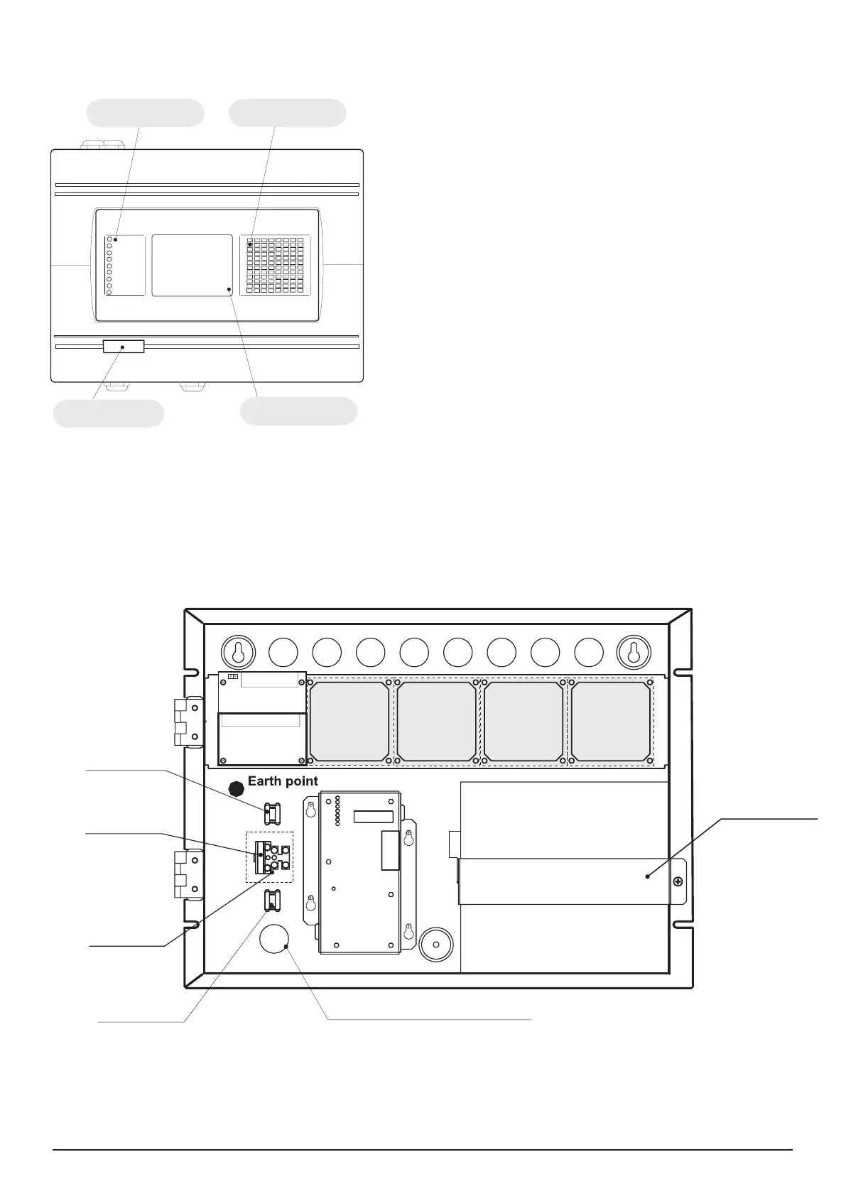
Figure 9.
Main view of the front panel.
Figure 10. Conguration of the basic modules in the system.
GENERAL FIRE - General FIRE Indication
PREALARM - Indication for zones in Pre-Alarm Condi-
tion
GENERAL FAULT - General FAULT Indication
SYSTEM FAULT - General SYSTEM FAULT Indication
SYSTEM SILENCE - General Indication for Silenced
Sounders
DELAY - General Indication for Active Delay in any of
the Outputs
DISABLE - General Indication for introduced Disability
TEST - General Indication for Test
POWER ON - Presence of mains power supply 230V
AC
LED indication
for the events
LED indication
for the zones
Heat printer
(option)
LCD Display
(320x240)
Power Supply
Unit
Loop
Controller
1
Loop
Controller
2
Loop
Controller
3
Loop
Controller
4
4 Relay
Module
I/O Module
Accumulator
Battery
12V / 18 Ah
Clamp for supporting
the main power
supply cable.
Clamp for supporting
the main power
supply cable.
A slow type fuse 2A
situated into
the terminal.
Terminal for
connection
between the mains
power supply and
the power source.
Mains power supply opening.
Metal clamp for
supporting
the battery.