Addressable Fire Panel IRIS - Installation and Programming Manual 11
The I/O Module (Figure 11) is a basic part of the re panel IRIS, see the description of the terminals below. The 4 Relay
Module is integrated onto the I/O Module and has 4 relays with programmable relay outputs.
ATTENTION: The Main Board could not work independently.
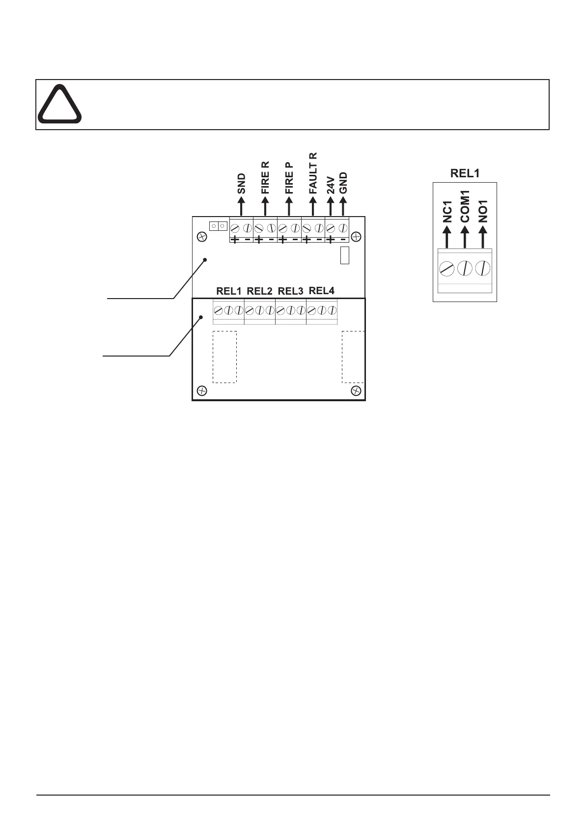
Figure 11. I/O Module with integrated 4 relay module.
Description of the Outputs Module terminal:
• +24V - DC Auxiliary outputs, 20 VA @ 0,3A;
• GND - Common earth
• SND - Monitored output for connecting of a sounder, 24 VDC / 0,3 A;
• FIRE R, FIRE P - Monitored outputs for connecting of auxiliary devices (e.g. signalling devices), 24V / 0,3A.
These outputs are activated in case of a re alarm condition.
• FAULT R - Monitored output for connecting of auxiliary devices, 24V / 0,3A.
This autput is activated in case of system trouble ot fault.
Description of the 4 relay module terminal:
• REL1, REL2, REL3 and REL4 - Programmable volt free change over relay contacts each, 110V/ 1A. Each
relay has one NO (normal open) and one NC (normal closed) contact with common lead on a terminal. When a relay
output is activated the NO contact is closed and the NC contact is opened - see Figure 11b.
Other:
- Ribbon cable interface connector to the front panel*;
- Interface connector for connecting Loop Expander Module*;
- Fuse 0,3A, type Resettable (on the back side of the I/O module);
- Mounting holes.
- Jumper for enable/disable indication for earth fault.
For example, if you want to enable the earth fault indication set a jumper on position 5.
The items and are situated on the back side of the Outputs module PCB.
Input-output
Module
4 Relay Module
a)
b)
Metal clamp for
supporting
the battery.