12 Addressable Fire Panel IRIS - Installation and Programming Manual
The monitored outputs SND, FIRE R, FIRE P and FAULT R, at activation, provide
24VDC@0,3A to the load connected between them and GND (the earthing point of the
panel).
It is necessary to connect in parallel to the last device in the loop a 10k terminate resistor,
so to ensure that the panel is able to detect any break or short circuit in the loop - see
Fig. 12.
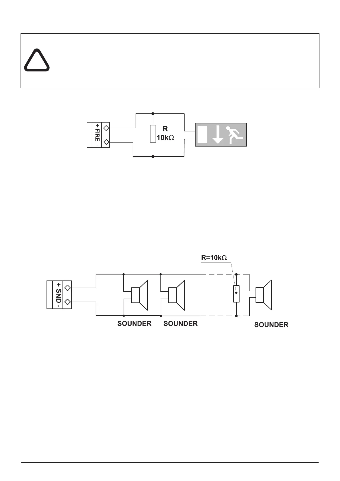
Figure 12. Example for connecting of end device (an illuminated exit sign)
to the Monitored FIRE Output.
To the monitored output SND could be connected several sounders - Figure 13. The maximum number of
sounders that could be connected in the circuit, depends on their total current consumption, which must not
exceed 0,3A.
Before connecting the last sounder in the circuit, parallel to it must be added resistor 10k.
Figure 13. Connecting of sounders.