Rev
A: 0611
5/98
Preparation for Use
TP04100A Interface
&
Applications
Front and rear panel interconnections are shown above.
Figure 2-9 shows the System Front Panel where the following system interconnections are made: DUT T and
DUT
K
thermocouple sensors (for thermocouple procedures, see Section 2-1
7).
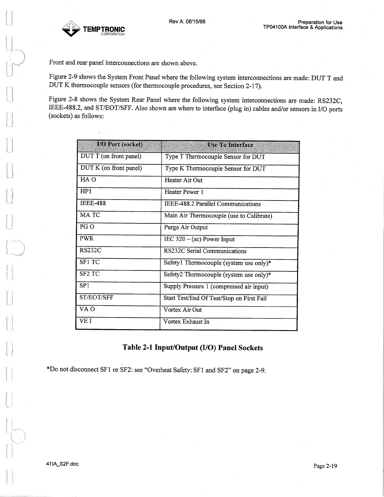
Figure 2-8 shows the System Rear Panel where the following system interconnections are made: RS232C,
IEEE-488.2, and ST/EOT/SFF. Also shown are where to interface (plug in) cables andlor sensors in I10 ports
(sockets)
as
follows:
I
DUT
K
(on fiont panel)
I
Type
K
Thermocouple Sensor for DUT
I
I/O
'Port
(socket)
DUT T (on front panel)
I
HAO
I
Heater Air Out
I
,
Use
To
Interface
Type T Thermocouple Sensor for DUT
I
MA
TC
I
Main Air Thermocouple (use to Calibrate)
I
HP
1
IEEE-488
Heater Power 1
IEEE-488.2 Parallel Communications
I
PWR
1
IEC 320
-
(ac) Power Input
I
I
I
RS232C
I
RS232C Serial Communications
I
PG
0
I
SF1 TC
I
Safety1 Thermocouple (system use only)*
I
Purge Air Output
I
SF2 TC
(
Safety2 Thermocouple (system use only)*
I
I
I
SP
1
I
Supply Pressure
1
(compressed air input)
I
I
VEI
(
Vortex Exhaust In
I
STIEOTISFF
VA
0
Table
2-1
InputIOutput (110)
Panel
Sockets
Start Test/End Of Test/Stop on First Fail
Vortex Air Out
*Do not disconnect SF 1 or SF2: see "Overheat Safety: SF
1
and SF2" on page 2-9.
Page 2-
19
Artisan Technology Group - Quality Instrumentation ... Guaranteed | (888) 88-SOURCE | www.artisantg.com
 Loading...