Rev A: 0611
5/98
System Operation
TP04100A Interface
&
Applications
3-7.6
Rotary
Encoder
The Rotary Encoder, to the right of the Display Screen, is used to step through and change various system
parameters and effectively replaces the traditionaI numeric keypad and enter key. The Encoder has two modes:
Step Mode and Change
ode.
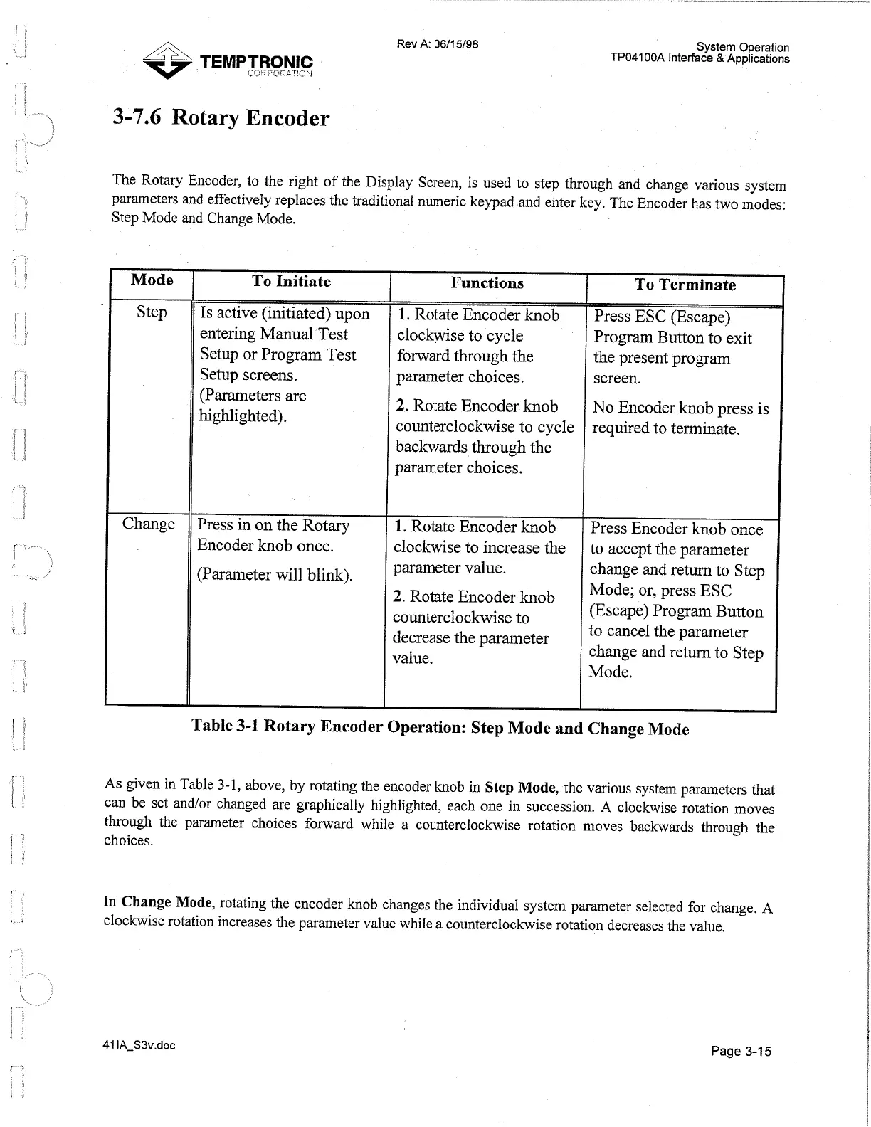
Mode
Step
Change
To Initiate
Is
active (initiated) upon
entering Manual Test
Setup or Program Test
Setup screens.
(Parameters are
highlighted).
Press in on the Rotary
Encoder knob once.
(Parameter will blink).
Functions
1.
Rotate Encoder knob
clockwise to cycle
forward through the
parameter choices.
2.
Rotate Encoder knob
counterclockwise to cycle
backwards through the
parameter choices.
1.
Rotate Encoder knob
clockwise to increase the
parameter value.
2.
Rotate Encoder knob
counterclockwise to
decrease the parameter
value.
To Terminate
Press ESC (Escape)
Program Button to exit
the present program
screen.
No Encoder knob press is
required to terminate.
Press Encoder knob once
to accept the parameter
change and return to Step
Mode; or, press ESC
(Escape) Program Button
to cancel the parameter
change and return to Step
Mode.
Table
3-1
Rotary Encoder Operation: Step Mode and Change Mode
As given in Table
3-1,
above, by rotating the encoder knob in Step Mode, the various system parameters that
can be set and/or changed are graphically highlighted, each one in succession.
A
clockwise rotation moves
through the parameter choices forward while a counterclockwise rotation moves backwards through the
choices.
In Change Mode, rotating the encoder knob changes the individual system parameter selected for change.
A
clockwise rotation increases the parameter value while a counterclockwise rotation decreases the value.
Page
3-15
Artisan Technology Group - Quality Instrumentation ... Guaranteed | (888) 88-SOURCE | www.artisantg.com
 Loading...