August 2021 Service and Repair Manual
Scissor Components
Part No. 1309020GT GS
™
-30m • 32m • 30 • 32 • 46 • 55 87
20 Pull out the red Emergency Stop button to the
on position at the ground controls.
21 Using the ground control menu buttons,
navigate to Service Override Mode. Select
Service Override Mode.
Note: The machine must be in Service Override
Mode to raise the platform. While in Service
Override Mode, only the GCON will operate with
limited functionality. The platform will raise a
predetermined amount of time and stop.
22 Raise the platform and rotate the safety arm
to the stowed position.
23 Fully lower the platform to the stowed
position.
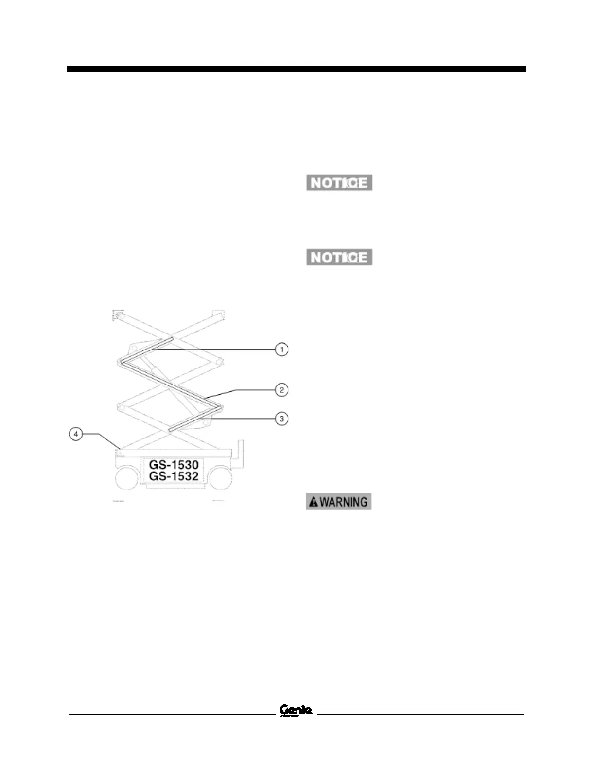
Cable bridge and platform height sensor
1 cable bridge 3
2 cable bridge 2
3 cable bridge 1
4 platform height sensor
24 Remove the platform. Refer to Repair
Procedure, How to Remove the Platform.
25 Remove the cables from the number 3 outer
arm (index #11) at the ground controls side.
Component damage hazard.
Cables can be damaged if they
are kinked or pinched.
26 Remove the cables from the number 3 cable
bridge and lay them off to the side.
Component damage hazard.
Cables can be damaged if they
are
kinked or pinched.
27 Attach a lifting strap from an overhead
supporting device to the number 3 outer arm
(index #11).
28 Remove the external snap rings and retaining
fasteners from the number 3 center pivot pins
(index #2).
29 Use a soft metal drift to remove the number
3 center pivot pins (index #2).
30 Remove the retaining fasteners from the
number 3 pivot pin (index #12) at the non-
steer end of the machine.
31 Use a soft metal drift to remove the number
3 pivot pin (index #12) from the non-steer end
of the machine. Remove the number 3 outer
arm (index #11) from the machine.
Crushing hazard. The number
3
outer arm may become
unbalanced and fall if not
properly supported when
removed from the machine.
32 Remove the number 3 cable bridge mounting
fasteners and remove the cable bridge from
the machine.
33 Attach a lifting strap from an overhead
supporting device to the lug on the rod end of
the lift cylinder for support. Do not apply any
lifting pressure.

 Loading...