August 2021 Service and Repair Manual
Diagnostics
Part No. 1309020GT GS
™
-30m • 32m • 30 • 32 • 46 • 55 179
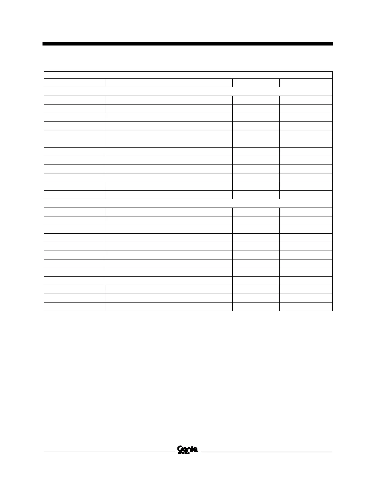
GCON I/O Map - Models with outriggers
Pin number Circuit function I/O Type Wire color
J1 – Grey
J1-01 Power, ECM Power Input Red
J1-02 Power, PCON Power Output Red
J1-03 Emergency stop, PCON Power Input White
J1-04 CAN High, PCON Data Bus Yellow
J1-05 CAN Low, PCON Data Bus Green
J1-06 Ground, PCON Ground Output Brown
J1-07 Ground, GCON Ground Input Brown
J1-08 Key switch, PCON Digital Input Black
J1-09 Key switch, GCON Digital Input White
J1-10 Emergency stop, GCON Digital Input White / Black
J1-11 Contact Alarm Digital Input Black
J1-12 Power, ECM Driver Power Input Red
J2 – Black
J2-01 Platform up coil Digital Output Orange
J2-02 Platform down coil Digital Output Orange / Black
J2-03 Steer left coil Digital Output Blue / Black
J2-04 Steer right coil Digital Output Blue
J2-05 Not used --- ---
J2-06 Not used --- ---
J2-07 Not used --- ---
J2-08 Motor controller enable Digital Output Green / White
J2-09 Not used --- ---
J2-10 Not used --- ---
J2-11 Not used --- ---
J2-12 Not used --- ---

 Loading...