Service and Repair Manual August 2021
Diagnostics
180 GS
™
-30m • 32m • 30 • 32 • 46 • 55 Part No. 1309020GT
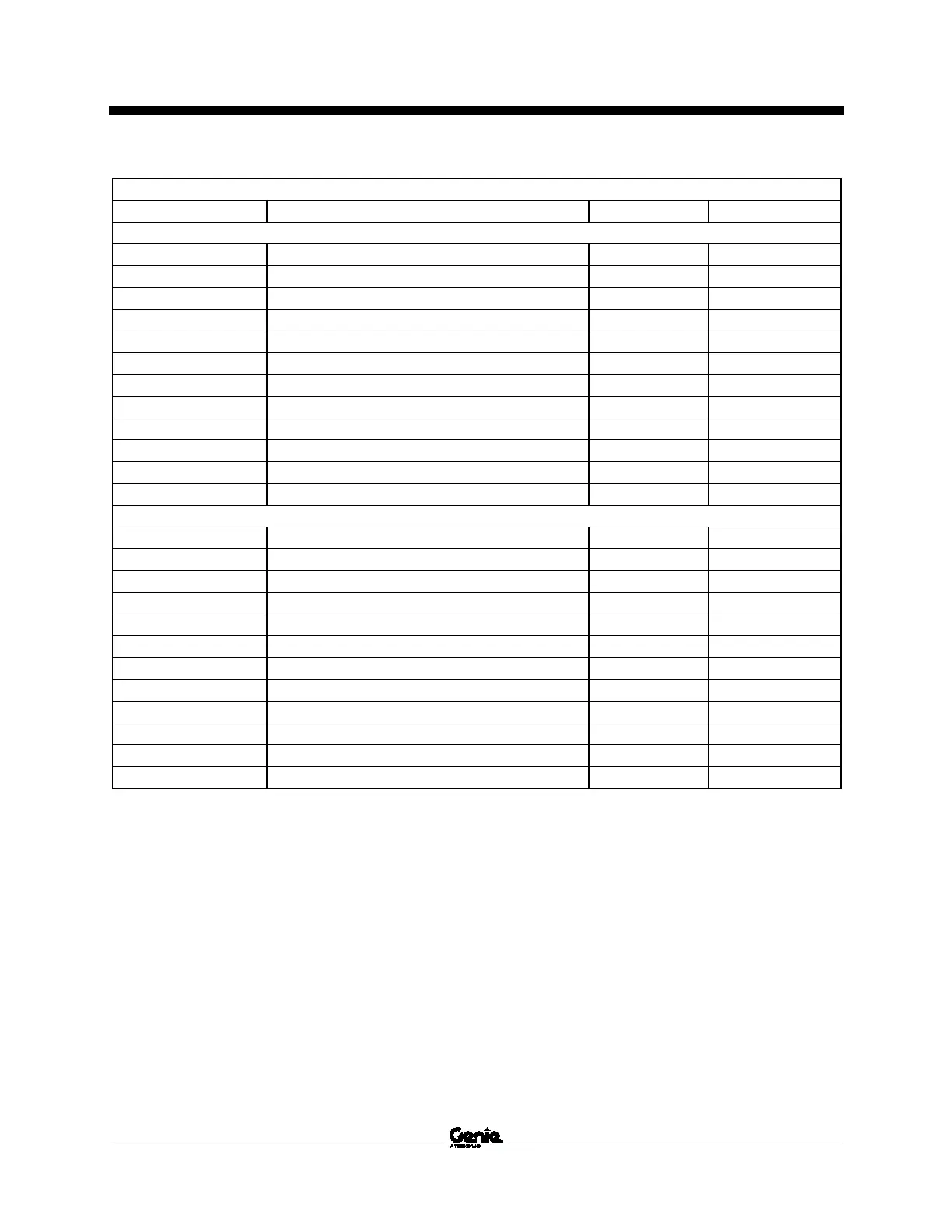
GCON I/O Map - Models with outriggers, (continued)
Pin number Circuit function I/O Type Wire color
J3 – Green
J3-01 Flashing beacon. PWM Digital Output Red / Black
J3-02 Alarm, GCON Digital Output Blue
J3-03 Sensor power Digital Output Red
J3-04 Not used --- ---
J3-05 Pothole limit switch - Models with electric drive Digital Input Orange / Red
J3-06 Not used --- ---
J3-07 Down limit switch Digital Input Orange
J3-08 Brake release - Models with electric drive Digital Input White / Red
J3-09 Pressure transducer Ground Input Blue / White
J3-10 Platform height sensor Ground Input Orange / White
J3-11 Not used --- ---
J3-12 Sensor ground Ground Input Black
J4 – Brown
J4-01 Left front outrigger pressure transducer Analog Input White
J4-02 Right front outrigger pressure transducer Analog Input Orange
J4-03 Left rear outrigger pressure transducer Analog Input Blue
J4-04 Right rear outrigger pressure transducer Analog Input Green
J4-05 Level sensor, X Axis Analog Input Blue / Black
J4-06 Level sensor, Y Axis Analog Input Blue / Red
J4-07 Left front outrigger coil Digital Output Red / White
J4-08 Right front outrigger coil Digital Output Orange / White
J4-09 Left rear outrigger coil Digital Output Blue / White
J4-10 Right rear outrigger coil Digital Output Green / White
J4-11 Outrigger extend coil Digital Output Green
J4-12 Outrigger retract coil Digital Output Green / Black

 Loading...