August 2021 Service and Repair Manual
Scissor Components
Part No. 1309020GT GS
™
-30m • 32m • 30 • 32 • 46 • 55 155
11 Tag, disconnect and plug the hydraulic hoses
on the lift cylinder. Cap the fittings on the
cylinder.
Bodily injury hazard. Spraying
hydraulic oil can penetrate and
burn skin. Loosen hydraulic
connections very slowly t
o allow
the oil pressure to dissipate
gradually. Do not allow oil to
squirt or spray.
12 Attach a lifting strap from an overhead
supporting device to the rod-end of the lift
cylinder.
13 Remove the fasteners from the lift cylinder
rod-end pivot pin. Use a soft metal drift to
remove the pin.
Crushing hazard. The lift
cylinder will fall if not properly
supported when the pivot pin is
removed.
14 Lower the cylinder onto the number 1 inner
arm cylinder plate.
15 Attach a lifting strap from an overhead
supporting device to the barrel-end of the lift
cylinder.
16 Remove the fasteners from the lift cylinder
barrel-end pivot pin. Use a soft metal drift to
remove the pin.
Crushing hazard. The lift
cylinder will fall if not properly
supported when the pivot pin is
removed.
17 Support and secure the lift cylinder to an
appropriate lifting device.
18 Remove the lift cylinder through the scissor
arms at the steer end of the machine.
Crushing hazard. The lift
cylinder will become unbalanced
and fall if not properly supported
and secured to the lifting device.
Component damage hazard. Be
careful not to damage the valve
or fittings on the cylinder while
removing it from the machine.
19 Install new cylinder, fittings, hoses and
pressure transducer.
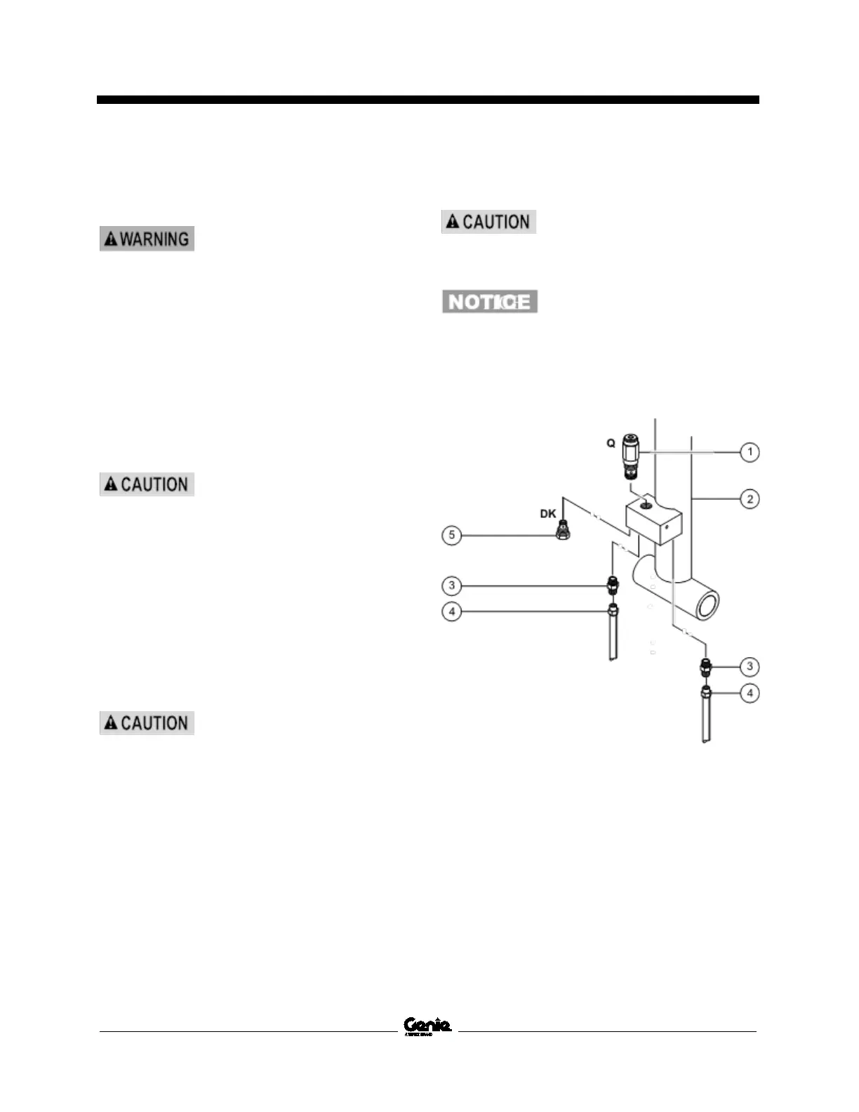
Upper Lift Cylinder GS-4046
1 relief valve, (schematic item Q)
2 lift cylinder
3 connector fitting
4 hydraulic hose
5 check valve, (schematic item DK)

 Loading...