LMK04821
,
LMK04826
,
LMK04828
www.ti.com
SNAS605AR –MARCH 2013–REVISED DECEMBER 2015
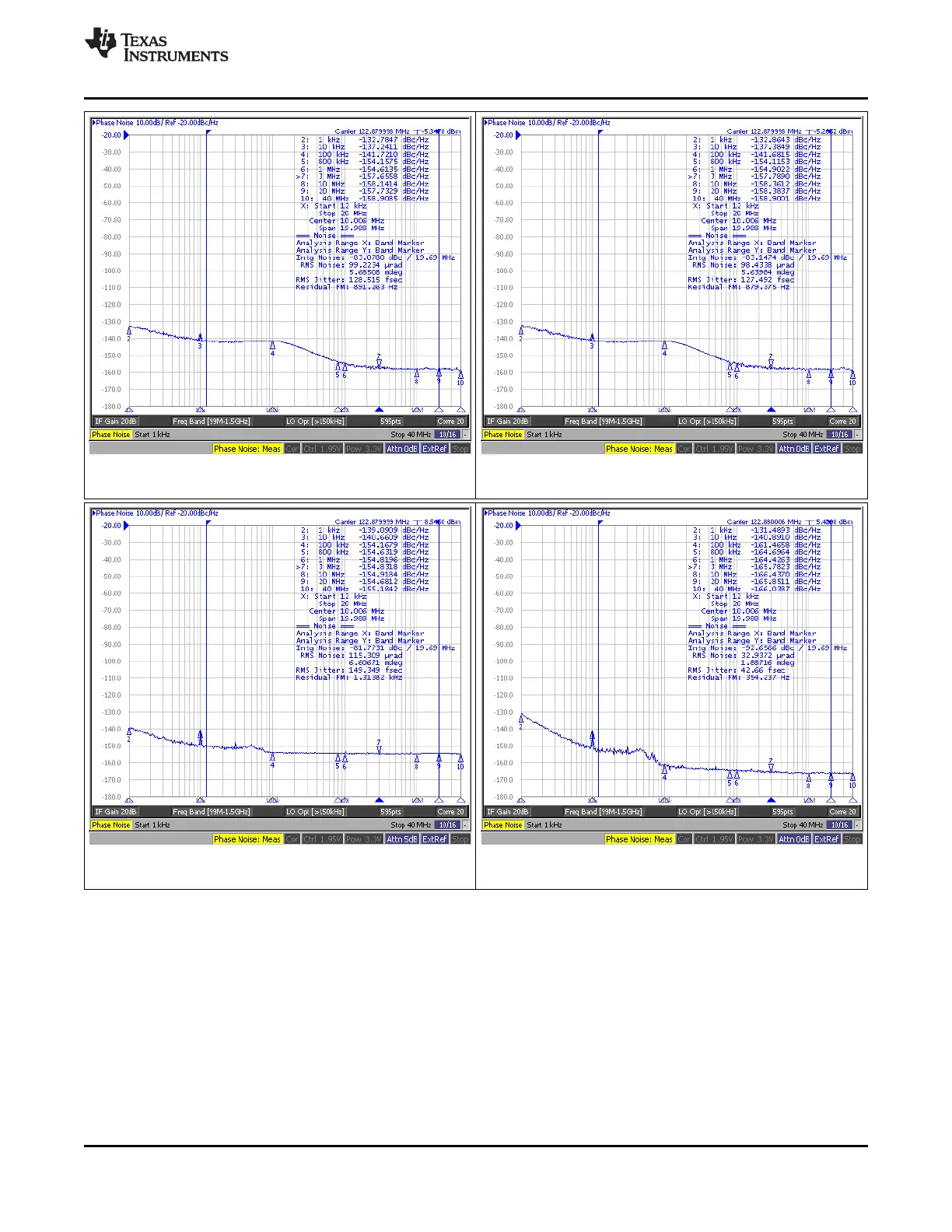
Figure 29. DCLKout10, 122.88 MHz, LVDS Figure 30. SDCLKout11, 122.88 MHz, LVDS
DCLKout0_1_IDL = 1, DCLKout0_1_ODL = 0 DCLKout0_1_IDL = 1, DCLKout0_1_ODL = 0
Figure 31. OSCout, 122.88 MHz, LVCMOS (Norm/Inv) Figure 32. Direct VCXO Measurement
Normal output measured, Inverse 50 Ω termination Open loop, holdover mode set
10.3 Do's and Don'ts
10.3.1 Pin Connection Recommendations
• V
CC
Pins and Decoupling: all V
CC
pins must always be connected.
• Unused Clock Outputs: leave unused clock outputs floating and powered down.
• Unused Clock Inputs: unused clock inputs can be left floating.
Copyright © 2013–2015, Texas Instruments Incorporated Submit Documentation Feedback 101
Product Folder Links: LMK04821 LMK04826 LMK04828