LMK04821
,
LMK04826
,
LMK04828
www.ti.com
SNAS605AR –MARCH 2013–REVISED DECEMBER 2015
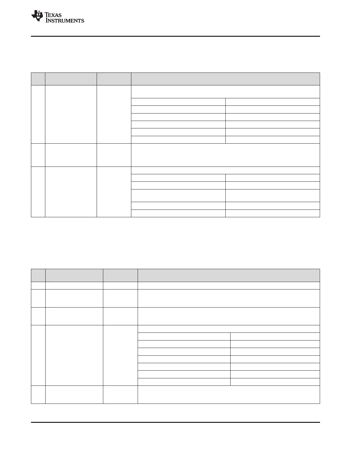
9.7.2.3 DCLKoutX_ADLY, DCLKoutX_ADLY_MUX, DCLKout_MUX
These registers control the analog delay properties for the device clocks.
Table 18. Registers 0x103, 0x10B, 0x113, 0x11B, 0x123, 0x12B, 0x133
POR
BIT NAME DESCRIPTION
DEFAULT
Device clock analog delay value. Setting this value results in a 500 ps timing delay in
additional to the delay of each 25 ps step. Effective range is 500 ps to 1075 ps.
Field Value Delay Value
0 (0x00) 0 ps
7:3 DCLKoutX_ALDY 0
1 (0x01) 25 ps
2 (0x02) 50 ps
... ...
23 (0x17) 575 ps
This register selects the input to the analog delay for the device clock. Used when
DCLKoutX_ADLY DCLKoutX_MUX = 3.
2 0
_MUX 0: Divided without duty cycle correction or half step.
(1)
1: Divided with duty cycle correction and half step.
This selects the input to the device clock buffer.
Field Value Mux Output
0 (0x0) Divider only
(1)
1:0 DCLKoutX_MUX 0
Divider with Duty Cycle Correction
1 (0x1)
and Half Step
2 (0x2) Bypass
3 (0x3) Analog Delay + Divider
(1) DCLKoutX_DIV = 1 is not valid.
9.7.2.4 DCLKoutX_HS, SDCLKoutY_MUX, SDCLKoutY_DDLY, SDCLKoutY_HS
These registers set the half step for the device clock, the SYSREF output MUX, the SYSREF clock digital delay,
and half step.
Table 19. Registers 0x104, 0x10C, 0x114, 0x11C, 0x124, 0x12C, 0x134
BIT NAME POR
DESCRIPTION
DEFAULT
7 NA 0 Reserved
Sets the device clock half step value. Half step must be zero (0) for a divide of 1.
6 DCLKoutX_HS 0 0: 0 cycles
1: -0.5 cycles
Sets the input the the SDCLKoutX outputs.
5 SDCLKoutY_MUX 0 0: Device clock output
1: SYSREF output
Sets the number of VCO cycles to delay the SDCLKout by.
Field Value Delay Cycles
0 (0x00) Bypass
1 (0x01) 2
4:1 SDCLKoutY_DDLY 0
2 (0x02) 3
... ...
10 (0x0A) 11
11 to 15 (0x0B to 0x0F) Reserved
Sets the SYSREF clock half step value.
0 SDCLKoutY_HS 0 0: 0 cycles
1: -0.5 cycles
Copyright © 2013–2015, Texas Instruments Incorporated Submit Documentation Feedback 57
Product Folder Links: LMK04821 LMK04826 LMK04828