1e6 × PLLX_WND_SIZE × f
PDX
PLLX_DLD_CNT
ppm =
LMK04821
,
LMK04826
,
LMK04828
www.ti.com
SNAS605AR –MARCH 2013–REVISED DECEMBER 2015
10 Applications and Implementation
10.1 Application Information
To assist customers in frequency planning and design of loop filters Texas Instrument's provides the Clock
Design Tool (www.ti.com/tool/clockdesigntool) and Clock Architect (www.ti.com/clockarchitect).
10.2 Typical Applications
10.2.1 Digital Lock Detect Frequency Accuracy
The digital lock detect circuit is used to determine PLL1 locked, PLL2 locked, and holdover exit events. A window
size and lock count register are programmed to set a ppm frequency accuracy of reference to feedback signals
of the PLL for each event to occur. When a PLL digital lock event occurs the PLL's digital lock detect is asserted
true. When the holdover exit event occurs, the device will exit holdover mode.
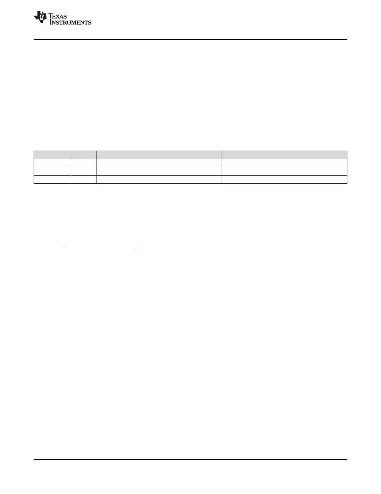
EVENT PLL WINDOW SIZE LOCK COUNT
PLL1 Locked PLL1 PLL1_WND_SIZE PLL1_DLD_CNT
PLL2 Locked PLL2 PLL2_WND_SIZE PLL2_DLD_CNT
Holdover exit PLL1 PLL1_WND_SIZE HOLDOVER_DLD_CNT
For a digital lock detect event to occur there must be a “lock count” number of phase detector cycles of PLLX
during which the time/phase error of the PLLX_R reference and PLLX_N feedback signal edges are within the
user programmable "window size." Since there must be at least "lock count" phase detector events before a lock
event occurs, a minimum digital lock event time can be calculated as "lock count" / f
PDX
where X = 1 for PLL1 or
2 for PLL2.
By using Equation 3, values for a "lock count" and "window size" can be chosen to set the frequency accuracy
required by the system in ppm before the digital lock detect event occurs:
(3)
The effect of the "lock count" value is that it shortens the effective lock window size by dividing the "window size"
by "lock count".
If at any time the PLLX_R reference and PLLX_N feedback signals are outside the time window set by "window
size", then the “lock count” value is reset to 0.
10.2.1.1 Minimum Lock Time Calculation Example
To calculate the minimum PLL2 digital lock time given a PLL2 phase detector frequency of 40 MHz and
PLL2_DLD_CNT = 10,000. Then the minimum lock time of PLL2 will be 10,000 / 40 MHz = 250 µs.
Copyright © 2013–2015, Texas Instruments Incorporated Submit Documentation Feedback 95
Product Folder Links: LMK04821 LMK04826 LMK04828