LMK04821
,
LMK04826
,
LMK04828
SNAS605AR –MARCH 2013–REVISED DECEMBER 2015
www.ti.com
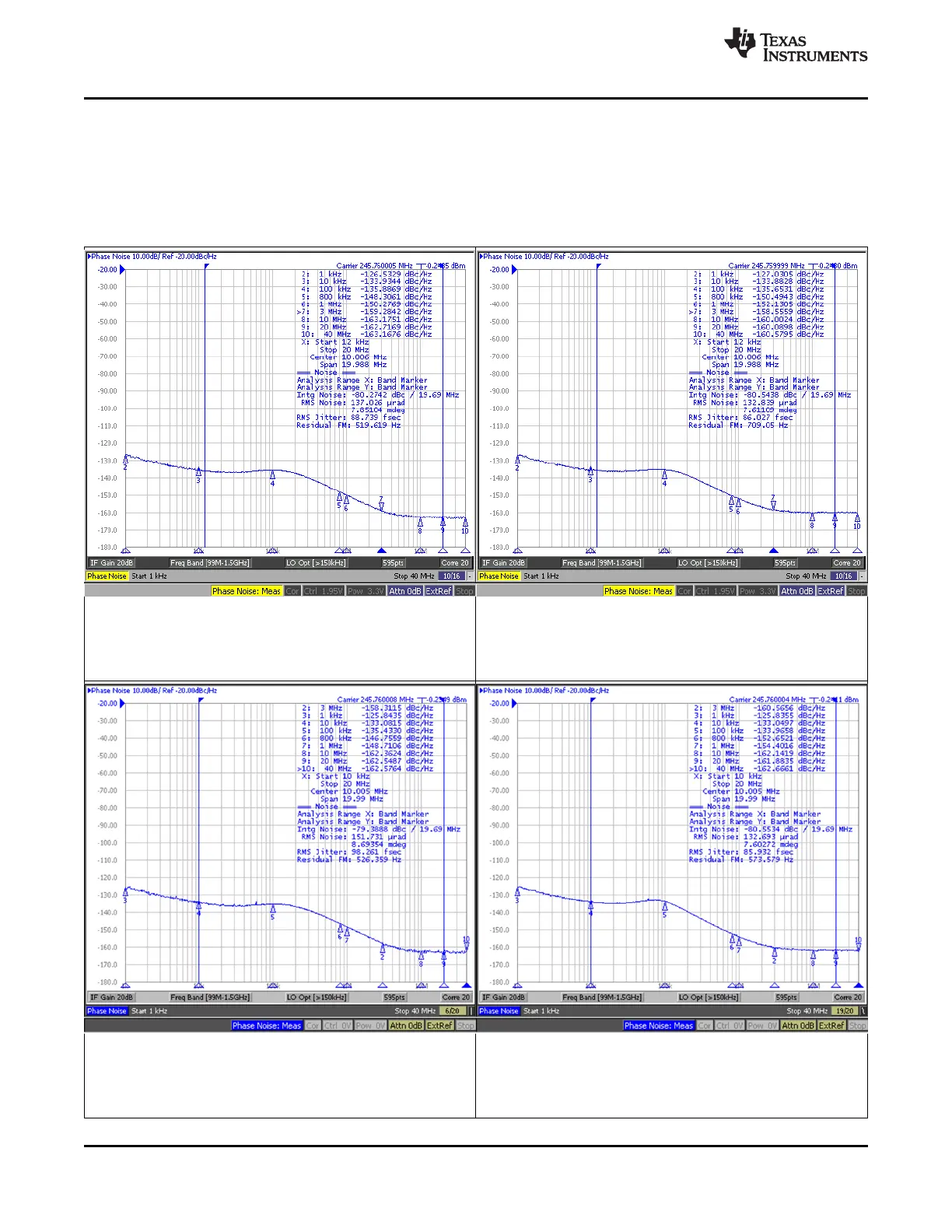
7.7 Typical Characteristics – Clock Output AC Characteristics
NOTE: These plots show performance at frequencies beyond the point at which the part is ensured to operate in order to give
an idea of the capabilities of the part. They do not imply any sort of ensured specification.
For Figure 2 through Figure 7, CLKout2_3_IDL=1; CLKout2_3_ODL=0; LVPECL20 with 240-Ω emitter resistors; DCLKout2
Frequency = 245.76 MHz; DCLKout2_MUX = 0 (Divider). For Figure 2 through Figure 5, Balun Prodyn BIB-100G. For
Figure 6 and Figure 7, Balun ADT2-1T+.
VCO_MUX = 0 (VCO0) PLL2 Loop Filter Bandwidth = 288 kHz VCO_MUX = 1 (VCO1) VCO1_DIV = 0 (÷2)
VCO0 = 1966.08 MHz PLL2 Phase Margin = 72° VCO = 2949.12 MHz PLL2 Loop Filter Bandwidth = 221 kHz
DCLKout2_DIV = 8 DCLKout2_DIV = 6 PLL2 Phase Margin = 70°
Figure 2. LMK04821 DCLKout2 Phase Noise Figure 3. LMK04821 DCLKout2 Phase Noise
VCO_MUX = 0 (VCO0) PLL2 Loop Filter Bandwidth = 303 kHz VCO_MUX = 1 (VCO1) PLL2 Loop Filter Bandwidth = 151 kHz
VCO0 = 1966.08 MHz PLL2 Phase Margin = 73° VCO = 2457.6 MHz PLL2 Phase Margin = 64°
DCLKout2_DIV = 8 DCLKout2_DIV = 10
Figure 4. LMK04826B DCLKout2 Phase Noise Figure 5. LMK04826B DCLKout2 Phase Noise
24 Submit Documentation Feedback Copyright © 2013–2015, Texas Instruments Incorporated
Product Folder Links: LMK04821 LMK04826 LMK04828