LMK04821
,
LMK04826
,
LMK04828
SNAS605AR –MARCH 2013–REVISED DECEMBER 2015
www.ti.com
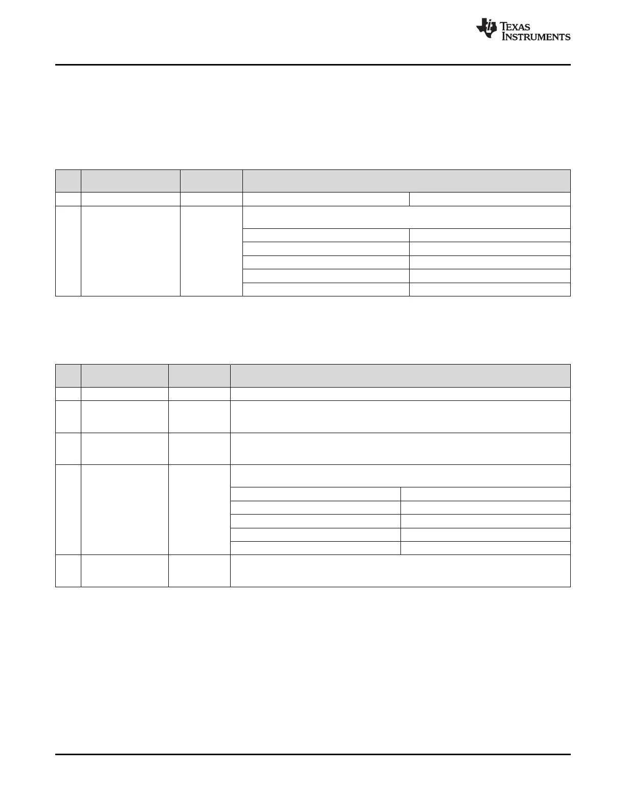
9.7.3.5 SYSREF_PULSE_CNT
This register sets the number of SYSREF pulses if SYSREF is not in continuous mode. See
SYSREF_CLKin0_MUX, SYSREF_MUX for further description of SYSREF's outputs.
Programming the register causes the specified number of pulses to be output if "SYSREF Pulses" is selected by
SYSREF_MUX and SYSREF functionality is powered up.
Table 27. Register 0x13E
POR
BIT NAME DESCRIPTION
DEFAULT
7:2 NA 0 Reserved
Sets the number of SYSREF pulses generated when not in continuous mode.
See SYSREF_CLKin0_MUX, SYSREF_MUX for more information on SYSREF modes.
Field Value Number of Pulses
0 (0x00) 1 pulse
1:0 SYSREF_PULSE_CNT 3
1 (0x01) 2 pulses
2 (0x02) 4 pulses
3 (0x03) 8 pulses
9.7.3.6 PLL2_NCLK_MUX, PLL1_NCLK_MUX, FB_MUX, FB_MUX_EN
This register controls the feedback feature.
Table 28. Register 0x13F
POR
BIT NAME DESCRIPTION
DEFAULT
7:5 NA 0 Reserved
Selects the input to the PLL2 N Divider
4 PLL2_NCLK_MUX 0 0: PLL Prescaler
1: Feedback Mux
Selects the input to the PLL1 N Delay.
3 PLL1_NCLK_MUX 0 0: OSCin
1: Feedback Mux
When in 0-delay mode, the feedback mux selects the clock output to be fed back into the
PLL1 N Divider.
Field Value Source
0 (0x00) DCLKout6
2:1 FB_MUX 0
1 (0x01) DCLKout8
2 (0x02) SYSREF Divider
3 (0x03) External
When using 0-delay, FB_MUX_EN must be set to 1 power up the feedback mux.
0 FB_MUX_EN 0 0: Feedback mux powered down
1: Feedback mux enabled
64 Submit Documentation Feedback Copyright © 2013–2015, Texas Instruments Incorporated
Product Folder Links: LMK04821 LMK04826 LMK04828