LMK04821
,
LMK04826
,
LMK04828
SNAS605AR –MARCH 2013–REVISED DECEMBER 2015
www.ti.com
9.7 Device Register Descriptions
The following section details the fields of each register, the Power On Reset Defaults, and specific descriptions of
each bit.
In some cases similar fields are located in multiple registers. In this case specific outputs may be designated as
X or Y. In these cases the X will represent even numbers from 0 to 12 and the Y will represent odd numbers
from 1 to 13. In the case where X and Y are both used in a bit name, then Y = X + 1.
9.7.1 System Functions
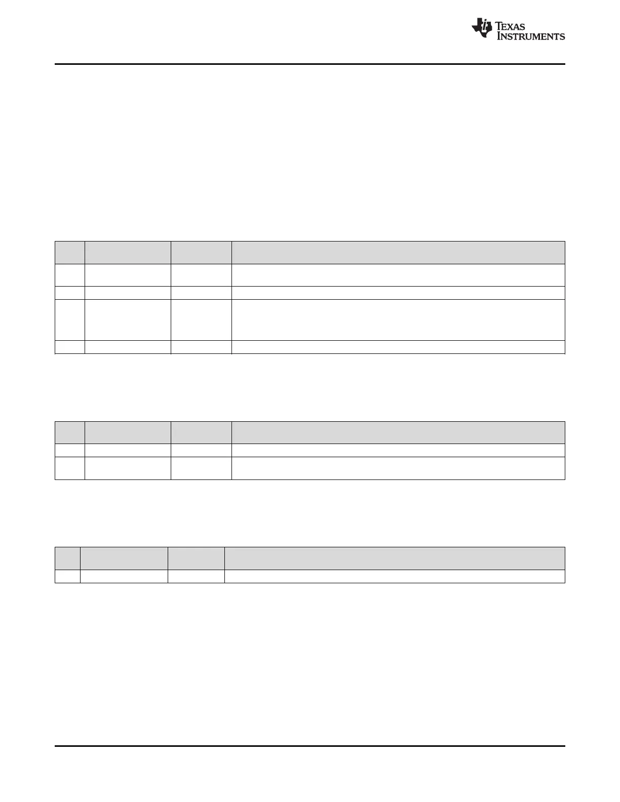
9.7.1.1 RESET, SPI_3WIRE_DIS
This register contains the RESET function.
Table 9. Register 0x000
BIT NAME POR
DESCRIPTION
DEFAULT
0: Normal Operation
7 RESET 0
1: Reset (automatically cleared)
6:5 NA 0 Reserved
Disable 3 wire SPI mode. 4 Wire SPI mode is enabled by selecting SPI Read back in one
of the output MUX settings. For example CLKin0_SEL_MUX.
4 SPI_3WIRE_DIS 0
0: 3 Wire Mode enabled
1: 3 Wire Mode disabled
3:0 NA NA Reserved
9.7.1.2 POWERDOWN
This register contains the POWERDOWN function.
Table 10. Register 0x002
POR
BIT NAME DESCRIPTION
DEFAULT
7:1 NA 0 Reserved
0: Normal Operation
0 POWERDOWN 0
1: Powerdown
9.7.1.3 ID_DEVICE_TYPE
This register contains the product device type. This is read only register.
Table 11. Register 0x003
POR
BIT NAME DESCRIPTION
DEFAULT
7:0 ID_DEVICE_TYPE 6 PLL product device type.
54 Submit Documentation Feedback Copyright © 2013–2015, Texas Instruments Incorporated
Product Folder Links: LMK04821 LMK04826 LMK04828