LMK04821
,
LMK04826
,
LMK04828
www.ti.com
SNAS605AR –MARCH 2013–REVISED DECEMBER 2015
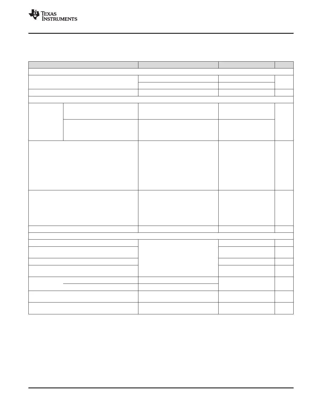
Electrical Characteristics (continued)
(3.15 V < V
CC
< 3.45 V, –40 °C < T
A
< 85 °C and T
PCB
≤ 105 °C. Typical values at V
CC
= 3.3 V, T
A
= 25 °C, at the
Recommended Operating Conditions and are not assured.)
PARAMETER TEST CONDITIONS MIN TYP MAX UNIT
DEFAULT POWER on RESET CLOCK OUTPUT FREQUENCY
LMK04826 235
Default output clock frequency at
f
CLKout-startup
MHz
device power on
(17)(18)
LMK04828 315
f
OSCout
OSCout Frequency
(7)
500 MHz
CLOCK SKEW and DELAY
DCLKoutX to SDCLKoutY
Same pair, Same format
(20)
F
CLK
= 245.76 MHz, R
L
= 100 Ω 25
SDCLKoutY_MUX = 0 (Device Clock)
AC coupled
(19)
|T
SKEW
| |ps|
Maximum DCLKoutX or SDCLKoutY
to DCLKoutX or SDCLKoutY Any pair, Same format
(20)
50
F
CLK
= 245.76 MHz, R
L
= 100 Ω SDCLKoutY_MUX = 0 (Device Clock)
AC coupled
SDCLKoutY_MUX = 1 (SYSREF)
SYSREF_DIV = 30
SYSREF_DDLY = 8 (global)
SYSREF to Device Clock setup time
SDCLKoutY_DDLY = 1 (2 cycles, local)
base reference.
DCLKoutX_MUX = 1 (Div+DCC+HS)
ts
JESD204B
See SYSREF to Device Clock –80 ps
DCLKoutX_DIV = 30
Alignment to adjust SYSREF to
DCLKoutX_DDLY_CNTH = 7
Device Clock setup time as required.
DCLKoutX_DDLY_CNTL = 6
DCLKoutX_HS = 0
SDCLKoutY_HS = 0
CLKin0_OUT_MUX = 0 (SYSREF Mux)
SYSREF_CLKin0_MUX = 1 (CLKin0)
SDCLKout1_PD = 0
t
PD
CLKin0_ Propagation Delay from CLKin0 to
SDCLKout1_DDLY = 0 (Bypass) 0.65 ns
SDCLKout1 SDCLKout1
SDCLKout1_MUX = 1 (SR)
EN_SYNC = 1
LVPECL16 /w 240 Ω
f
ADLY
max Maximum analog delay frequency DCLKoutX_MUX = 4 1536 MHz
LVDS CLOCK OUTPUTS (DCLKoutX, SDCLKoutY, and OSCout)
V
OD
Differential Output Voltage 395 |mV|
Change in Magnitude of V
OD
for
ΔV
OD
–60 60 mV
T = 25 °C, DC measurement
complementary output states
AC coupled to receiver input
V
OS
Output Offset Voltage 1.125 1.25 1.375 V
R
L
= 100 Ω differential termination
Change in V
OS
for complementary
ΔV
OS
35 |mV|
output states
Output Rise Time 20% to 80%, R
L
= 100 Ω, 245.76 MHz
T
R
/ T
F
180 ps
Output Fall Time 80% to 20%, R
L
= 100 Ω
I
SA
Output short circuit current - single Single-ended output shorted to GND
–24 24 mA
I
SB
ended T = 25 °C
Output short circuit current -
I
SAB
Complimentary outputs tied together –12 12 mA
differential
(17) OSCout will oscillate at start-up at the frequency of the VCXO attached to OSCin port.
(18) LMK04821 has no DCLKoutX or SDCLKoutY outputs which oscillate at power on. Only OSCout oscillates at power on.
(19) Equal loading and identical clock output configuration on each clock output is required for specification to be valid. Specification not valid
for delay mode.
(20) LVPECL uses 120 Ω emitter resistor, LVDS and HSDS uses 560 Ω shunt.
Copyright © 2013–2015, Texas Instruments Incorporated Submit Documentation Feedback 19
Product Folder Links: LMK04821 LMK04826 LMK04828