87
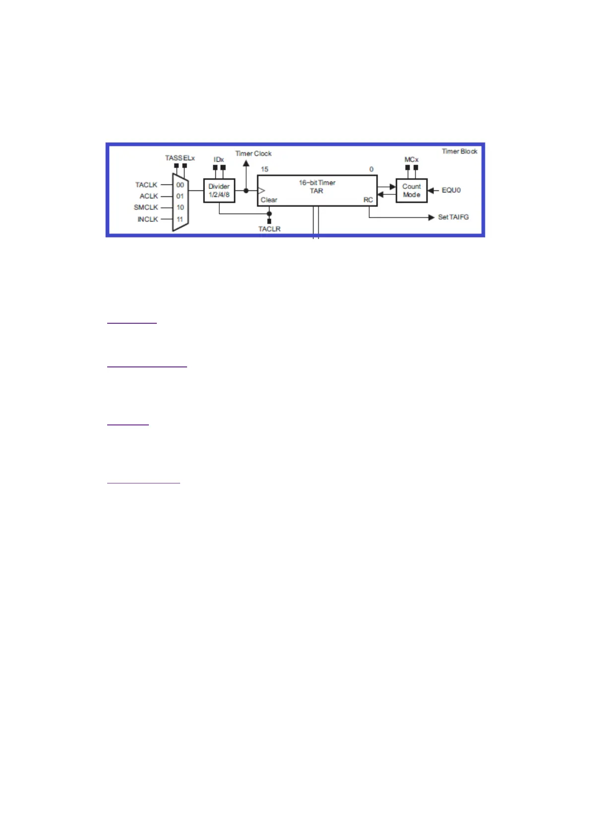
The diagram below shows that clock sources we can use for a Timer A module. It can be clocked with
two internal clock sources – ACLK and SMCLK or with two external clock sources – TACLK and INCLK.
Actually, INCLK and TACLK are same but one is complementary of the other. These external clocks can
be used to make the timer module work as counter.
Next, we have a prescaler to scale down selected clock source followed by the counter block. What’s
interesting about MSP430 timers is the counter’s mode of operation. There are four modes of counter
operation and these modes define counting direction:
• Stop Mode
It is basically a hold state. All timer registers are retained and the timer is halted.
• Continuous Mode
In this mode, the timer counts up from 0 to top value (here 0xFFFF or 65535 in 16-bit Timer
A3) and then rolls over to zero.
• Up Mode
This mode is same as continuous mode except for the top value. The top value of the timer is
set by the value in TACCR0.
• Up/Down Mode
In this mode, the timer counts from 0 to TACCR0 value and then rolls back from that value to
0. The period of the timer is twice the TACCR0 counts.
Then we have timer interrupt just as in any other microcontroller.