89
Input capture is somewhat just the opposite of PWM generation. In capture mode, CC channels can
be used to record time-related info of an incoming waveform. A timer in this mode can be left to run
on its own. When a waveform edge is detected, the corresponding time count of the timer is stored
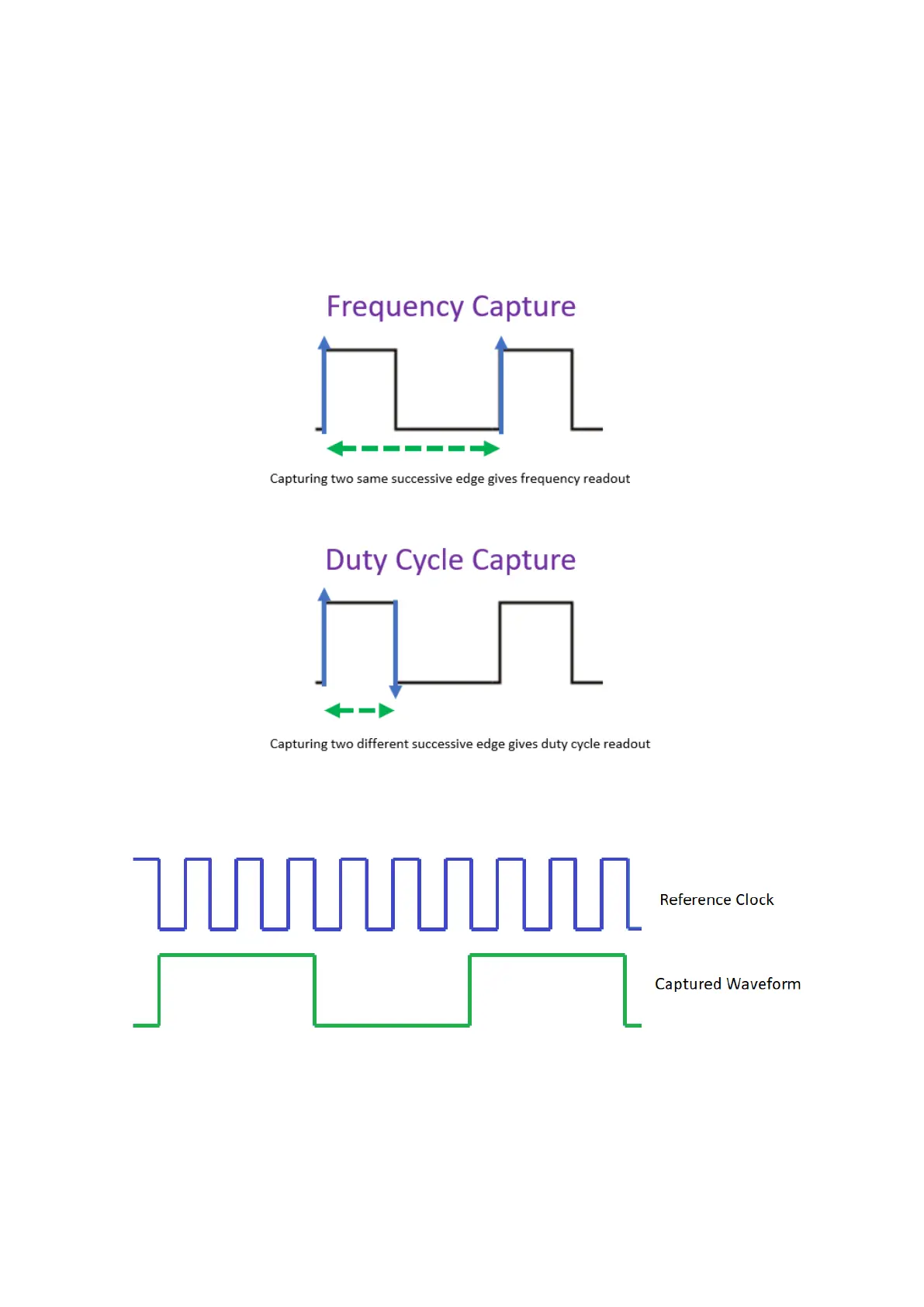
in CC register. With two such consecutive captures, we get a difference in timer’s time counts. This
difference can be used to measure frequency if the captured events are alike (two successive
rising/falling edges) or duty cycle if the captured events are different (different edges). Again, TACCRn
stores the time capture when a capture event occurs.
As an example, check the arbitrary timing diagram below:
Here four falling edges of reference clock (timer clock) is equal to the high or on time of the captured
waveform. Since the reference clock’s period is known, we can deduce pulse width.