TMS320F2810, TMS320F2811, TMS320F2812
TMS320C2810, TMS320C2811, TMS320C2812
www.ti.com
SPRS174T –APRIL 2001–REVISED MAY 2012
6.27 External Interface Ready-on-Write Timing With One External Wait State
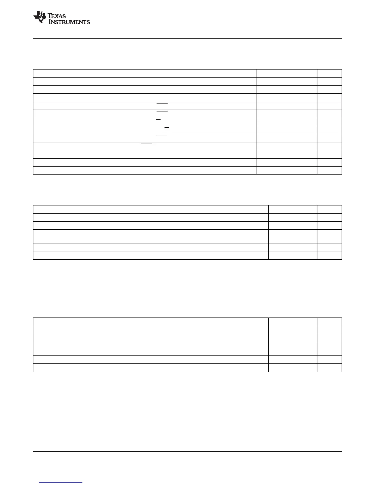
Table 6-39. External Memory Interface Write Switching Characteristics (Ready-on-Write, 1 Wait State)
PARAMETER MIN MAX UNIT
t
d(XCOH-XZCSL)
Delay time, XCLKOUT high to zone chip-select active-low 1 ns
t
d(XCOHL-XZCSH)
Delay time, XCLKOUT high or low to zone chip-select inactive-high –2 3 ns
t
d(XCOH-XA)
Delay time, XCLKOUT high to address valid 2 ns
t
d(XCOHL-XWEL)
Delay time, XCLKOUT high/low to XWE low 2 ns
t
d(XCOHL-XWEH)
Delay time, XCLKOUT high/low to XWE high 2 ns
t
d(XCOH-XRNWL)
Delay time, XCLKOUT high to XR/W low 1 ns
t
d(XCOHL-XRNWH)
Delay time, XCLKOUT high/low to XR/W high –2 1 ns
t
en(XD)XWEL
Enable time, data bus driven from XWE low 0 ns
t
d(XWEL-XD)
Delay time, data valid after XWE active-low 4 ns
t
h(XA)XZCSH
Hold time, address valid after zone chip-select inactive-high
(1)
ns
t
h(XD)XWE
Hold time, write data valid after XWE inactive-high TW – 2
(2)
ns
t
dis(XD)XRNW
Maximum time for DSP to release the data bus after XR/W inactive-high 4 ns
(1) During inactive cycles, the XINTF address bus will always hold the last address put out on the bus. This includes alignment cycles.
(2) TW = trail period, write access. See Table 6-30.
Table 6-40. Synchronous XREADY Timing Requirements (Ready-on-Write, 1 Wait State)
(1)
MIN MAX UNIT
t
su(XRDYsynchL)XCOHL
Setup time, XREADY (synchronous) low before XCLKOUT high/low 15 ns
t
h(XRDYsynchL)
Hold time, XREADY (synchronous) low 12 ns
Earliest time XREADY (synchronous) can go high before the sampling
t
e(XRDYsynchH)
3 ns
XCLKOUT edge
t
su(XRDYsynchH)XCOHL
Setup time, XREADY (synchronous) high before XCLKOUT high/low 15 ns
t
h(XRDYsynchH)XZCSH
Hold time, XREADY (synchronous) held high after zone chip-select high 0 ns
(1) The first XREADY (synchronous) sample occurs with respect to E in Figure 6-35:
E = (XWRLEAD + XWRACTIVE) t
c(XTIM)
When first sampled, if XREADY (synchronous) is found to be high, then the access will complete. If XREADY (synchronous) is found to
be low, it will be sampled again each t
c(XTIM)
until it is found to be high.
For each sample, setup time from the beginning of the access can be calculated as:
D = (XWRLEAD + XWRACTIVE + n – 1) t
c(XTIM)
– t
su(XRDYsynchL)XCOHL
where n is the sample number (n = 1, 2, 3, and so forth).
Table 6-41. Asynchronous XREADY Timing Requirements (Ready-on-Write, 1 Wait State)
(1)
MIN MAX UNIT
t
su(XRDYasynchL)XCOHL
Setup time, XREADY (asynchronous) low before XCLKOUT high/low 11 ns
t
h(XRDYasynchL)
Hold time, XREADY (asynchronous) low 8 ns
Earliest time XREADY (asynchronous) can go high before the sampling
t
e(XRDYasynchH)
3 ns
XCLKOUT edge
t
su(XRDYasynchH)XCOHL
Setup time, XREADY (asynchronous) high before XCLKOUT high/low 11 ns
t
h(XRDYasynchH)XZCSH
Hold time, XREADY (asynchronous) held high after zone chip-select high 0 ns
(1) The first XREADY (synchronous) sample occurs with respect to E in Figure 6-36:
E = (XWRLEAD + XWRACTIVE – 2) t
c(XTIM)
When first sampled, if XREADY (asynchronous) is found to be high, then the access will complete. If XREADY (asynchronous) is found
to be low, it will be sampled again each t
c(XTIM)
until it is found to be high.
For each sample, setup time from the beginning of the access can be calculated as:
D = (XWRLEAD + XWRACTIVE – 3 + n) t
c(XTIM)
– t
su(XRDYasynchL)XCOHL
where n is the sample number (n = 1, 2, 3, and so forth).
Copyright © 2001–2012, Texas Instruments Incorporated Electrical Specifications 137
Submit Documentation Feedback
Product Folder Link(s): TMS320F2810 TMS320F2811 TMS320F2812 TMS320C2810 TMS320C2811 TMS320C2812