TMS320F2810, TMS320F2811, TMS320F2812
TMS320C2810, TMS320C2811, TMS320C2812
SPRS174T –APRIL 2001–REVISED MAY 2012
www.ti.com
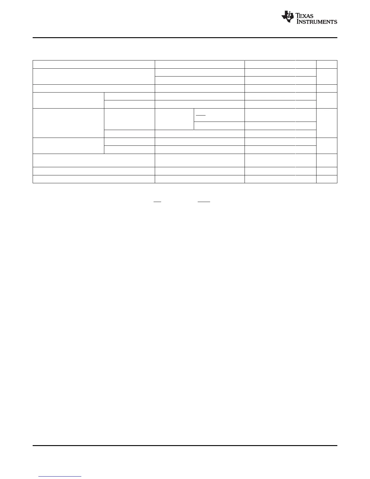
6.3 Electrical Characteristics Over Recommended Operating Conditions
(Unless Otherwise Noted)
PARAMETER TEST CONDITIONS MIN TYP MAX UNIT
V
OH
High-level output voltage I
OH
= I
OH
MAX 2.4 V
I
OH
= 50 µA V
DDIO
– 0.2
V
OL
Low-level output voltage I
OL
= I
OL
MAX 0.4 V
I
IL
(1)
Input current With pullup V
DDIO
= 3.3 V, V
IN
= 0 V –80 –140 –190 µA
(low level)
With pulldown V
DDIO
= 3.3 V, V
IN
= 0 V ±2
I
IL
(2)
Input current With pullup V
DDIO
= 3.3 V, All I/Os
(3)
(including –80 –140 –190 µA
(low level) V
IN
= 0 V XRS) except EVB
GPIOB/EVB –13 –25 –35
With pulldown V
DDIO
= 3.3 V, V
IN
= 0 V ±2
I
IH
Input current With pullup V
DDIO
= 3.3 V, V
IN
= V
DD
±2 µA
(high level)
With pulldown
(4)
V
DDIO
= 3.3 V, V
IN
= V
DD
28 50 80
I
OZ
Leakage current (for pins without internal V
O
= V
DDIO
or 0 V ±2 µA
PU/PD), high-impedance state (off-state)
C
i
Input capacitance 2 pF
C
o
Output capacitance 3 pF
(1) Applicable to C281x devices
(2) Applicable to F281x devices
(3) The following pins have no internal PU/PD: GPIOE0, GPIOE1, GPIOF0, GPIOF1, GPIOF2, GPIOF3, GPIOF12, GPIOG4, and GPIOG5.
(4) The following pins have an internal pulldown: XMP/MC, TESTSEL, and TRST.
92 Electrical Specifications Copyright © 2001–2012, Texas Instruments Incorporated
Submit Documentation Feedback
Product Folder Link(s): TMS320F2810 TMS320F2811 TMS320F2812 TMS320C2810 TMS320C2811 TMS320C2812