S
S
LSPCLK
456 123 0
0123
SPI Bit Rate
State Control
SPICCR.3 - 0
SPIBRR.6 - 0
Clock
Polarity
SPICCR.6
Clock
Phase
SPICTL.3
Talk
SPICTL.1
M
S
M
M
S
Master/Slave
SPICTL.2
SPI Char
SPISIMO
SPISOMI
SPICLK
SW2
S
M
M
S
SW3
To CPU
M
SW1
SPIDAT.15 - 0
16
16
SPITXINT
TX
FIFO
Interrupt
RX
FIFO
Interrupt
SPISTE
(A)
RX FIFO Registers
SPIRXBUF
SPIFFTX.14
SPIFFENA
RX FIFO _15
- - - - -
RX FIFO _1
RX FIFO _0
TX FIFO Registers
SPITXBUF
- - - - -
TX FIFO _15
TX FIFO _0
TX FIFO _1
16
SPITXBUF Buffer Register
SPIRXBUF Buffer Register
SPICTL.0
SPI
INT ENA
SPI
INT FLAG
SPISTS.6
Receiver
Overrun Flag
Overrun
INT ENA
SPISTS.7
SPICTL.4
SPIINT/SPIRXINT
RX Interrupt
Logic
TX Interrupt
Logic
SPIFFOVF
FLAG
SPIFFRX.15
SPIDAT Data Register
16
TMS320F2810, TMS320F2811, TMS320F2812
TMS320C2810, TMS320C2811, TMS320C2812
SPRS174T –APRIL 2001–REVISED MAY 2012
www.ti.com
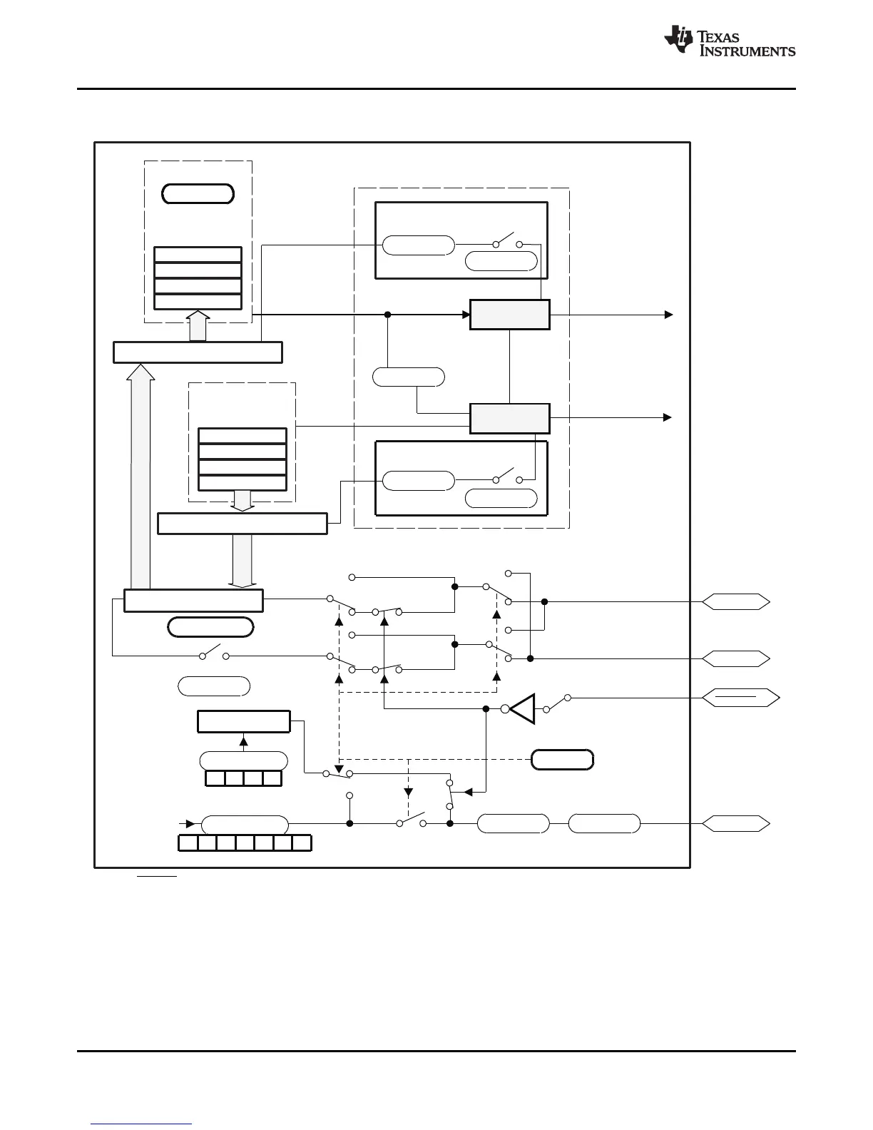
Figure 4-11 is a block diagram of the SPI in slave mode.
A. SPISTE is driven low by the master for a slave device.
Figure 4-11. Serial Peripheral Interface Module Block Diagram (Slave Mode)
82 Peripherals Copyright © 2001–2012, Texas Instruments Incorporated
Submit Documentation Feedback
Product Folder Link(s): TMS320F2810 TMS320F2811 TMS320F2812 TMS320C2810 TMS320C2811 TMS320C2812