TMS320F2810, TMS320F2811, TMS320F2812
TMS320C2810, TMS320C2811, TMS320C2812
www.ti.com
SPRS174T –APRIL 2001–REVISED MAY 2012
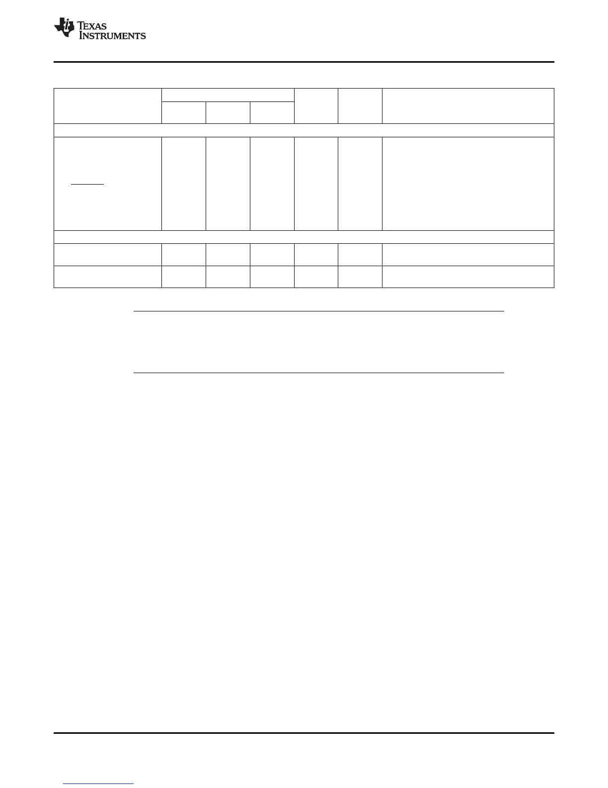
Table 2-2. Signal Descriptions
(1)
(continued)
PIN NO.
NAME I/O/Z
(2)
PU/PD
(3)
DESCRIPTION
179-BALL 176-PIN 128-PIN
GHH/ZHH PGF PBK
GPIOF OR XF CPU OUTPUT SIGNAL
This pin has three functions:
1. XF – General-purpose output pin.
2. XPLLDIS – This pin is sampled during
reset to check whether the PLL must be
GPIOF14 -
A11 140 101 I/O PU
disabled. The PLL will be disabled if this
XF_XPLLDIS (O)
pin is sensed low. HALT and STANDBY
modes cannot be used when the PLL is
disabled.
3. GPIO – GPIO function
GPIOG OR SCI-B SIGNALS
GPIO or SCI asynchronous serial port transmit
GPIOG4 - SCITXDB (O) P14 90 66 I/O/Z –
data
GPIO or SCI asynchronous serial port receive
GPIOG5 - SCIRXDB (I) M13 91 67 I/O/Z –
data
NOTE
Other than the power supply pins, no pin should be driven before the 3.3-V rail has reached
recommended operating conditions. However, it is acceptable for an I/O pin to ramp along
with the 3.3-V supply.
Copyright © 2001–2012, Texas Instruments Incorporated Introduction 25
Submit Documentation Feedback
Product Folder Link(s): TMS320F2810 TMS320F2811 TMS320F2812 TMS320C2810 TMS320C2811 TMS320C2812