101
TMS570LS0714
www.ti.com
SPNS226E –JUNE 2013–REVISED NOVEMBER 2016
Submit Documentation Feedback
Product Folder Links: TMS570LS0714
Peripheral Information and Electrical SpecificationsCopyright © 2013–2016, Texas Instruments Incorporated
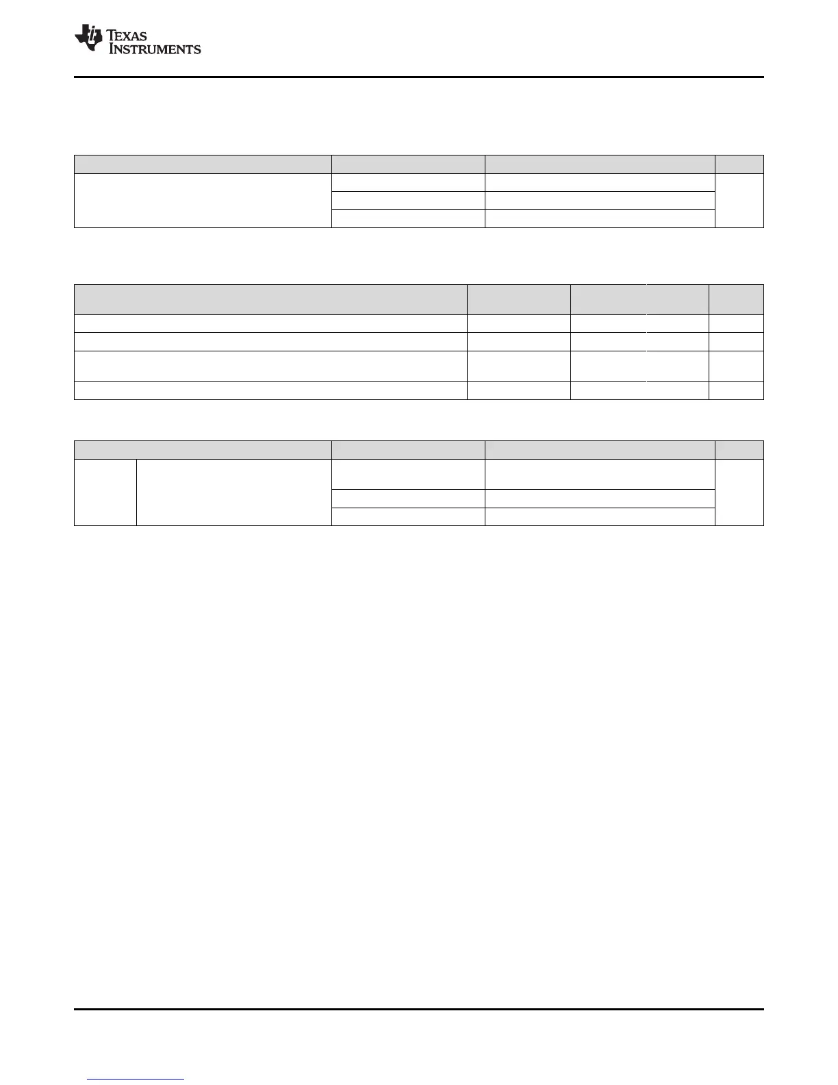
(1) The filter width is 6 VCLK4 cycles
7.2.8 Enhanced Translator-Pulse Width Modulator (ePWMx) Timings
Table 7-8. ePWMx Timing Requirements
TEST CONDITIONS MIN MAX UNIT
t
w(SYNCIN)
Synchronization input pulse width
Asynchronous 2 t
c(VCLK4)
cyclesSynchronous 2 t
c(VCLK4)
Synchronous, with input filter 2 t
c(VCLK4)
+ filter width
(1)
Table 7-9. ePWMx Switching Characteristics
PARAMETER
TEST
CONDITIONS
MIN MAX UNIT
t
w(PWM)
Pulse duration, ePWMx output high or low 33.33 ns
t
w(SYNCOUT)
Synchronization Output Pulse Width 8 t
c(VCLK4)
cycles
t
d(PWM)tza
Delay time, trip input active to PWM forced high, or
Delay time, trip input active to PWM forced low
No pin load 25 ns
t
d(TZ-PWM)HZ
Delay time, trip input active to PWM Hi-Z 20 ns
(1) For more information on the clock divider fields: HSPCLKDIV and CLKDIV, see the ePWM chapter of the device-specific Technical
Reference Manual (TRM).
Table 7-10. ePWMx Trip-Zone Timing Requirements
TEST CONDITIONS MIN MAX UNIT
t
w(TZ)
Pulse duration, TZn input low
Asynchronous
2 * HSPCLKDIV * CLKDIV *
t
c(VCLK4)
(1)
cycles
Synchronous 2 t
c(VCLK4)
Synchronous, with input filter 2 t
c(VCLK4)
+ filter width
 Loading...


