ECAPx
(x = 1, 2, 3, 4, 5, or 6)
eCAPx
double
sync
(x = 1 through 6)
6 VCLK4
Cycles Filter
103
TMS570LS0714
www.ti.com
SPNS226E –JUNE 2013–REVISED NOVEMBER 2016
Submit Documentation Feedback
Product Folder Links: TMS570LS0714
Peripheral Information and Electrical SpecificationsCopyright © 2013–2016, Texas Instruments Incorporated
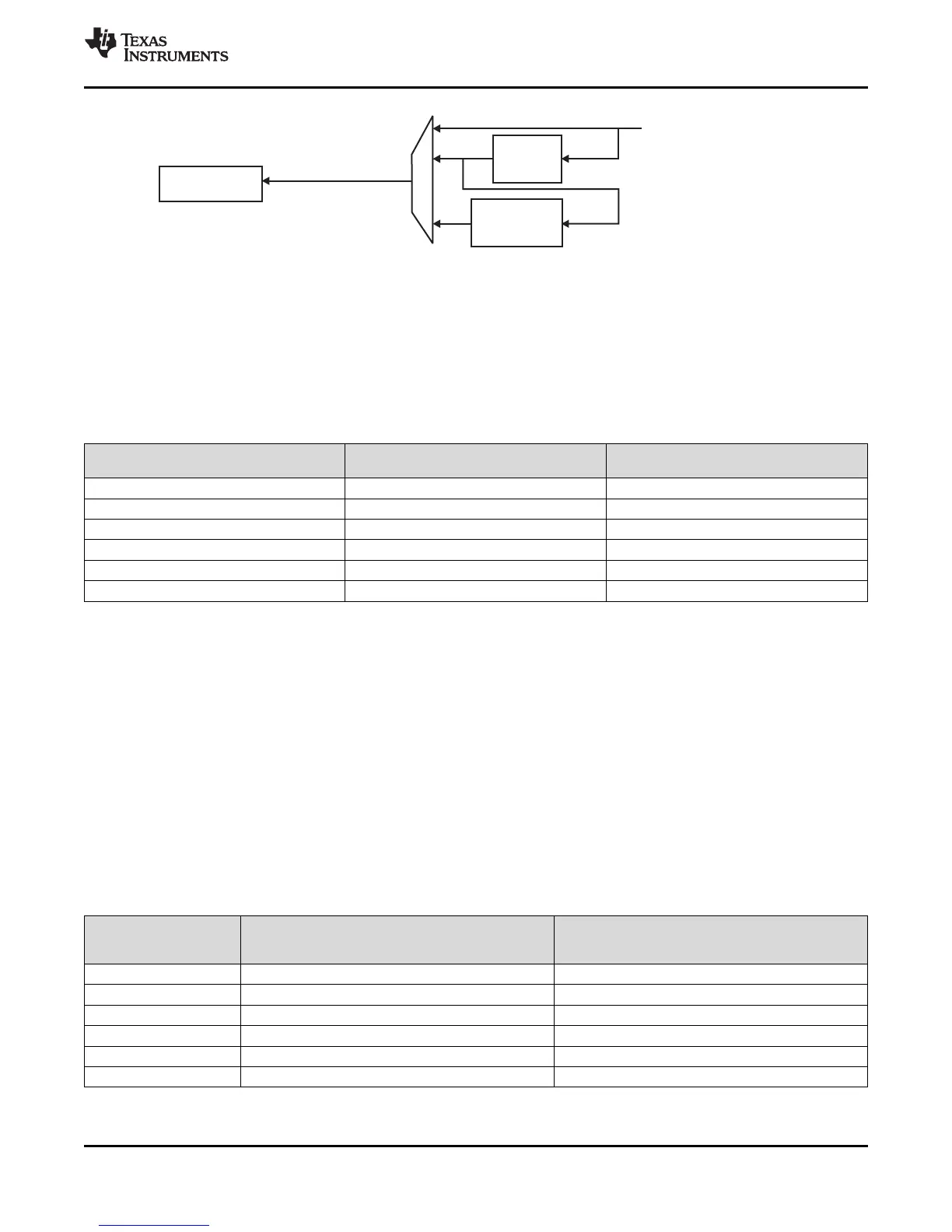
Figure 7-7. eCAPx Input Synchronization Selection Detail
7.3.1 Clock Enable Control for eCAPx Modules
Each of the eCAPx modules have a clock enable (ECAPxENCLK). These signals must be generated from
a device-level control register. When SYS_nRST is active-low, the clock enables are ignored and the
ECAPx logic is clocked so that it can reset to a proper state. When SYS_nRST goes in-active high, the
state of clock enable is respected.
Table 7-11. eCAPx Clock Enable Control
eCAP MODULE INSTANCE
CONTROL REGISTER TO
ENABLE CLOCK
DEFAULT VALUE
eCAP1 PINMMR39[0] 1
eCAP2 PINMMR39[8] 1
eCAP3 PINMMR39[16] 1
eCAP4 PINMMR39[24] 1
eCAP5 PINMMR40[0] 1
eCAP6 PINMMR40[8] 1
(1) The filter width is 6 VCLK4 cycles.
The default value of the control registers to enable the clocks to the eCAPx modules is 1. This means that
the VCLK4 clock connections to the eCAPx modules are enabled by default. The application can choose
to gate off the VCLK4 clock to any eCAPx module individually by clearing the respective control register
bit.
7.3.2 PWM Output Capability of eCAPx
When not used in capture mode, each of the eCAPx modules can be used as a single-channel PWM
output. This is called the Auxiliary PWM (APWM) mode of operation of the eCAPx modules. For more
information, see the eCAP module chapter of the device-specific TRM.
7.3.3 Input Connection to eCAPx Modules
The input connection to each of the eCAPx modules can be selected between a double-VCLK4-
synchronized input or a double-VCLK4-synchronized and filtered input, as shown in Table 7-12.
Table 7-12. Device-Level Input Connection to eCAPx Modules
INPUT SIGNAL
CONTROL FOR
DOUBLE-SYNCHRONIZED
CONNECTION TO eCAPx
CONTROL FOR
DOUBLE-SYNCHRONIZED AND
FILTERED CONNECTION TO eCAPx
(1)
eCAP1 PINMMR43[2:0] = 001 PINMMR43[2:0] = 010
eCAP2 PINMMR43[10:8] = 001 PINMMR43[10:8] = 010
eCAP3 PINMMR43[18:16] = 001 PINMMR43[18:16] = 010
eCAP4 PINMMR43[26:24] = 001 PINMMR43[26:24] = 010
eCAP5 PINMMR44[2:0] = 001 PINMMR44[2:0] = 010
eCAP6 PINMMR44[10:8] = 001 PINMMR44[10:8] = 010
 Loading...


