142
TMS570LS0714
SPNS226E –JUNE 2013–REVISED NOVEMBER 2016
www.ti.com
Submit Documentation Feedback
Product Folder Links: TMS570LS0714
Peripheral Information and Electrical Specifications Copyright © 2013–2016, Texas Instruments Incorporated
(1) The MASTER bit (SPIGCR1.0) is cleared and the CLOCK PHASE bit (SPIFMTx.16) is set.
(2) If the SPI is in slave mode, the following must be true: tc(SPC)S ≤ (PS + 1) tc(VCLK), where PS = prescale value set in SPIFMTx.[15:8].
(3) For rise and fall timings, see Table 7-2.
(4) t
c(VCLK)
= interface clock cycle time = 1 /f
(VCLK)
(5) When the SPI is in Slave mode, the following must be true:
For PS values from 1 to 255: t
c(SPC)S
≥ (PS +1)t
c(VCLK)
≥ 40 ns, where PS is the prescale value set in the SPIFMTx.[15:8] register bits.
For PS values of 0: t
c(SPC)S
= 2t
c(VCLK)
≥ 40 ns.
(6) The active edge of the SPICLK signal referenced is controlled by the CLOCK POLARITY bit (SPIFMTx.17).
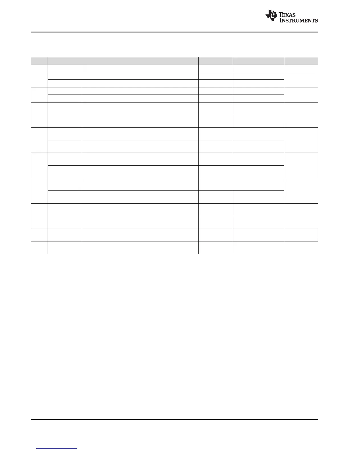
Table 7-39. SPI Slave Mode External Timing Parameters (CLOCK PHASE = 1, SPICLK = input, SPISIMO =
input, and SPISOMI = output)
(1)(2)(3)(4)
NO. PARAMETER MIN MAX UNIT
1 t
c(SPC)S
Cycle time, SPICLK
(5)
40 ns
2
(6)
t
w(SPCH)S
Pulse duration, SPICLK high (clock polarity = 0) 14
ns
t
w(SPCL)S
Pulse duration, SPICLK low (clock polarity = 1) 14
3
(6)
t
w(SPCL)S
Pulse duration, SPICLK low (clock polarity = 0) 14
ns
t
w(SPCH)S
Pulse duration, SPICLK high (clock polarity = 1) 14
4
(6)
t
d(SOMI-SPCL)S
Delay time, SPISOMI data valid after SPICLK low
(clock polarity = 0)
t
rf(SOMI)
+ 20
ns
t
d(SOMI-SPCH)S
Delay time, SPISOMI data valid after SPICLK high
(clock polarity = 1)
t
rf(SOMI)
+ 20
5
(6)
t
h(SPCL-SOMI)S
Hold time, SPISOMI data valid after SPICLK high
(clock polarity =0)
2
ns
t
h(SPCH-SOMI)S
Hold time, SPISOMI data valid after SPICLK low (clock
polarity =1)
2
6
(6)
t
su(SIMO-SPCH)S
Setup time, SPISIMO before SPICLK high (clock
polarity = 0)
4
ns
t
su(SIMO-SPCL)S
Setup time, SPISIMO before SPICLK low (clock polarity
= 1)
4
7
(6)
t
v(SPCH-SIMO)S
High time, SPISIMO data valid after SPICLK high
(clock polarity = 0)
2
ns
t
v(SPCL-SIMO)S
High time, SPISIMO data valid after SPICLK low (clock
polarity = 1)
2
8
t
d(SPCH-SENAH)S
Delay time, SPIENAn high after last SPICLK high
(clock polarity = 0)
1.5t
c(VCLK)
2.5t
c(VCLK)
+t
r(ENAn)
+22
ns
t
d(SPCL-SENAH)S
Delay time, SPIENAn high after last SPICLK low (clock
polarity = 1)
1.5t
c(VCLK)
2.5t
c(VCLK)
+t
r(ENAn)
+22
9 t
d(SCSL-SENAL)S
Delay time, SPIENAn low after SPICSn low (if new data
has been written to the SPI buffer)
t
f(ENAn)
t
c(VCLK)
+t
f(ENAn)
+27
ns
10 t
d(SCSL-SOMI)S
Delay time, SOMI valid after SPICSn low (if new data
has been written to the SPI buffer)
t
c(VCLK)
2t
c(VCLK)
+t
rf(SOMI)
+28 ns
 Loading...


