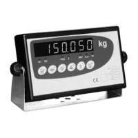
Installation
4-4
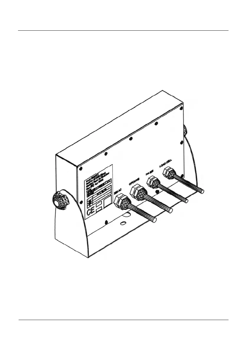
4.4 IP65 Assembly
(Only available in the stainless steel version)
To make the appropiate connections in the IP65 indicator (see 5.3), remove the rear
cover and pass each connection cord through the designated cable-gland screwing each of
them to guarantee that they are properly locked. If any of the connections is not established, do
not drill the cable-gland inside part.
After passing each cable through the cable-gland, pass them twice through the inside
part of the circular ferrites supplied with the equipment.
Figure 4.4.1 IP 65