Connector description
5-1
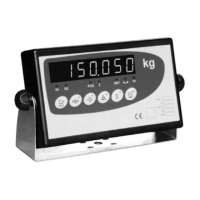
5 Connector Description
Figure 5.1 Connectors
5.1 Load cell Connector
Use a SUBD-9 aerial male connector to connect the load cell to the indicator. Weld
wires in accordance with the following tables. For the 6 wire connection it is advisable to bridge
1-6 and 5-9 pins in order to double the excitation signal contact surface.
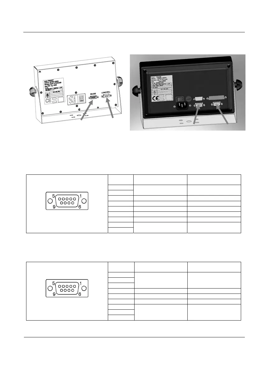
SUB-D 9 aerial male connector
Pin allocation
welding's side view
PIN SIGNAL
UTILCELL
Cell Code
1
EXC + Green
6
2 Sense + Blue
7 SIG + Red
3 Shield -
8 SIG- White
4 Sense - Yellow
5
EXC - Black
9
Table 5.1.1 6 Wire PIN Allocation
If a 4 wire cable is used, bridge 1-6-2 pins (EXC+ and SENSE+) and 4-5-9 (EXC-
and SENSE-) in the aerial connector.
SUB-D 9 aerial male connector
Pin allocation
welding's side view
PIN SIGNAL
UTILCELL
Cell Code
1
EXC + Green
6
2
7 SIG + Red
3 Shield -
8 SIG- White
4
EXC - Black
5
9
Table 5.1.2 4 Wire PIN Allocation
Load cell
RS-232
Load cell
RS-232