Connector description
5-6
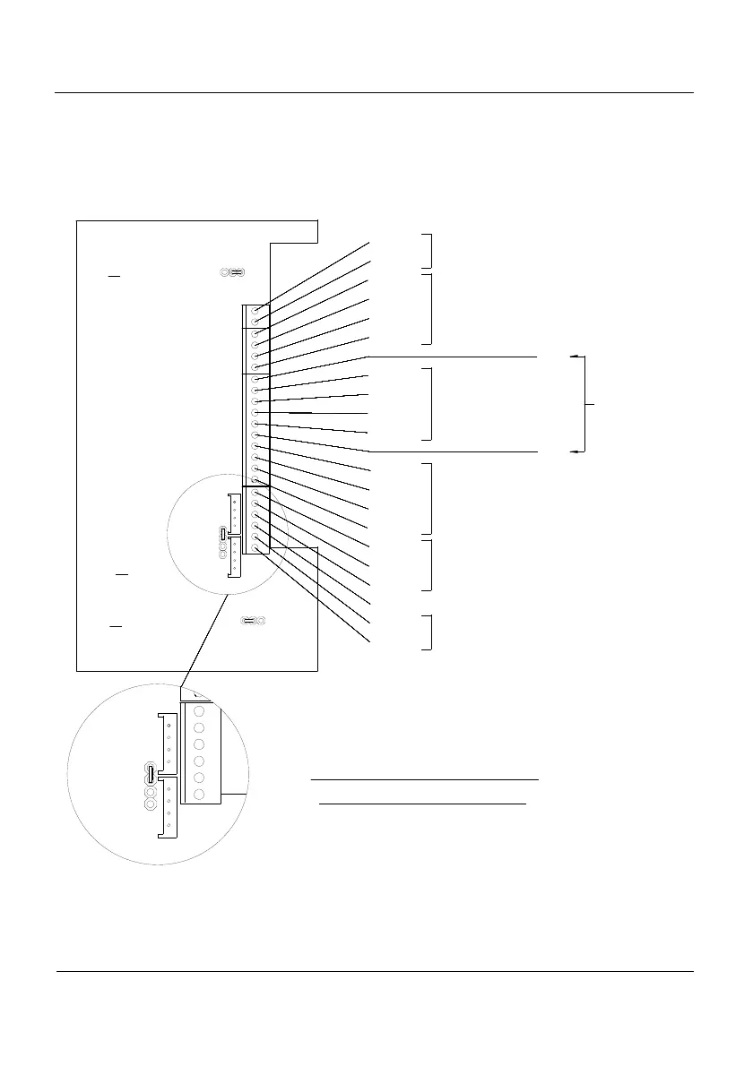
5.6 IP65 Multioption connection
For the connections of the IP65 Multioption indicator as well as the connections of the IP65
(see 5.3) perform the connections shown in figure 5.6.1.
JP3
ABC
JP4
J1
BCA
JP2
A
B
C
D
J2
RTS
Tx
GND
RTS
Rx
Tx
D-OUT 4
D-OUT 3
D-OUT 2
D-OUT 1
IN4
IN3
IN2
IN1
V-
V+
I-
I+
DATA-
DATA+
JP3
A - B RTERM OFF
B - C RTERM ON
A - B RTS OFF
B - C RTS-Rx/Tx ON
JP4
C - D RTS-Tx ON
B - C RS-485 OFF
A - B RS-485 ON
JP2
RS-485
Analog Output
Digital Input
Digital Output
RS-232 (Rx/Tx)
RS-232 (Tx)
GND
Vext
Power Supply
J2
D
A
B
C
JP4
J1
J1 : CONNECTION RS-232 (Rx/Tx)
J2 : CONNECTION RS-232 (Tx)
CONNECTION FOR VERSION WITH CONNECTORS
Figura 5.6.1 Multioption IP 65 Connection