Connector description
5-3
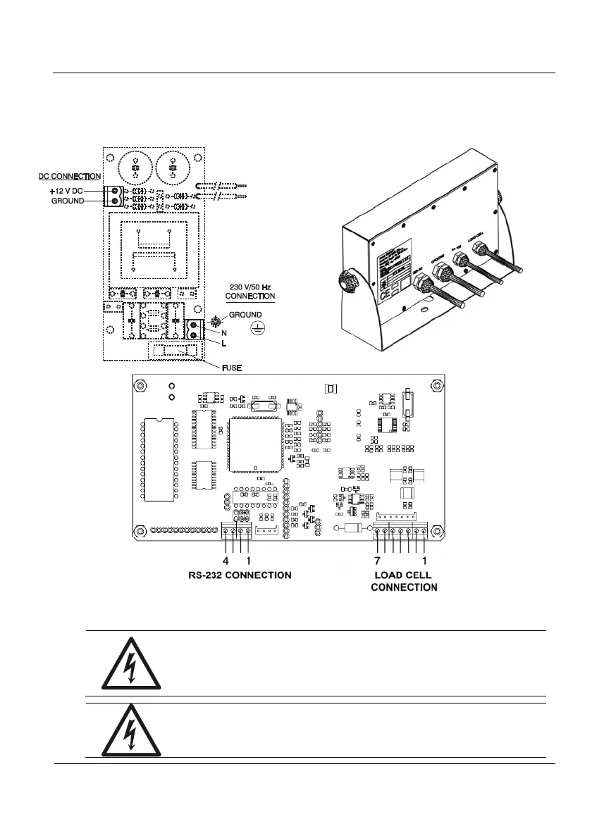
5.3 IP65 Connections
Use the cable-gland that you will find in the equipment rear side for the IP65 indicator
connections. Make the connections as shown in figure 5.3.1.
Figure 5.3.1 IP 65 Connection
WARNING-SHOCK HAZARD
Due to the risk of electrical shock, this instrument must
be operated only by qualified personnel and be
unplugged from the power supply.
WARNING-SHOCK HAZARD
Due to the risk of electrical shock, the cabinet of the
equipment must be connected to the ground wire.