Introduction
1-1
1 Introducction
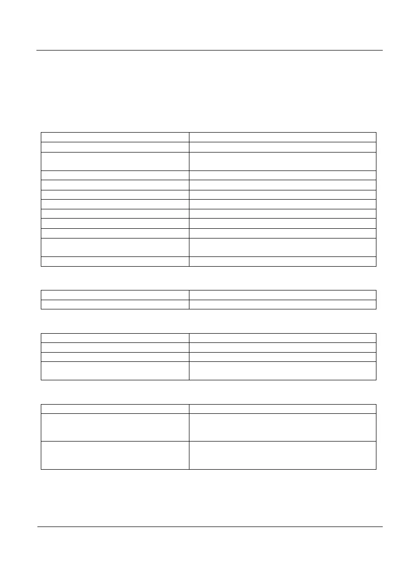
1.1 Indicator Characteristics
1.1.1 Load Cell Connection
Full scale input signal ±3 mV/V
Input impedance
200 M
(typical)
Internal resolution Converter AD 24 bits,16700000 counts
(± 8350000)
Measurement rate 50 measurements per second
Linearity error
0.01 % of measurement level
Zero stability 150 nV/ºC máx.
Span stability 3.5 ppm/ºC máx.
Excitation voltage 6.1 ± 0.5 VDC
Transducer minimum resistance
85Ω (4 cellsx350Ω, 8 cellsx700Ω)
Transducer maximum resistance
1000 k
Wire length 400 m/mm
máx. (6 wires)
30 m/mm
2
máx. (4 wires)
Input overload ± 12 V
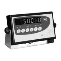
1.1.2 Operator Interface
Main display 7 digit LED 20 mm
Keyboard Keyboard with 6 keys
1.1.3 Serial Communications
Port Tx/Rx: Bi-directional RS-232C
Optional RS-485, RS-232C only transmission
Transmission rates 19200, 9600, 4800, 2400 y 1200 bauds
Number of bits and parity 8 bits no parity, 7 bits even parity and 7 bits odd
parity
1.1.4 Input/Output Options
4 digital inputs V
ILOW
= 0.8V; V
IHIGH
= 2V; V
IMAX
= 30V
4 digital outputs Open collector outputs; V
OLOW
= 0.5V
V
OHIGH
= V
EXT
– 1.2V; I
ILOW
= 200mA (max)
Range V
EXT
= 5V – 24V
Analog output Galvanic insulation output, 14-bits D/A
Voltage output: 0 –10.5V (nom); load > 1kΩ
Current output: 0 – 21mA; loop resistance<500 Ω