Connector description
5-4
Load cell Connection
RS-232 Connection
PIN SIGNAL
UTILCELL
Load cell Code
PIN SIGNAL
1 SIG + Red 1 TxD
2 SIG- White 2 RxD
3 Shield - 3 RTS
4 Sense + Blue 4 GND
5 Sense - Yellow
6 EXC - Black
7 EXC + Green
Table 5.3.2 6 Wire PIN Allocation
If a 4 wire power cord is used, bridge 4-7 pins (EXC+ and SENSE+) and 5-6 (EXC-
and SENSE-) in the aerial connector.
Load cell Connection
RS-232 Connection
PIN SIGNAL
UTILCELL
Load cell Code
PIN SIGNAL
1 SIG + Red 1 TxD
2 SIG- White 2 RxD
3 Shield - 3 RTS
5-6 EXC - Black 4 GND
4-7 EXC + Green
Tabla 5.3.3 4 Wire PIN Allocation
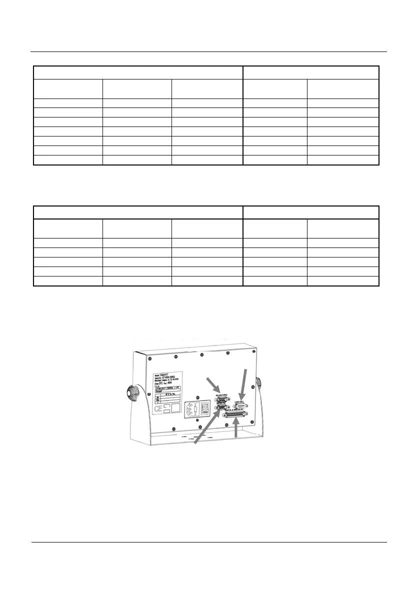
5.4 Multioption connection
(Only available in the stainless steel version)
Figura 5.4.1 Multioption Connectors
Load cell
RS-232
Tx
Digit./Analog I/O
RS-232
(Tx/Rx)