Connector description
5-7
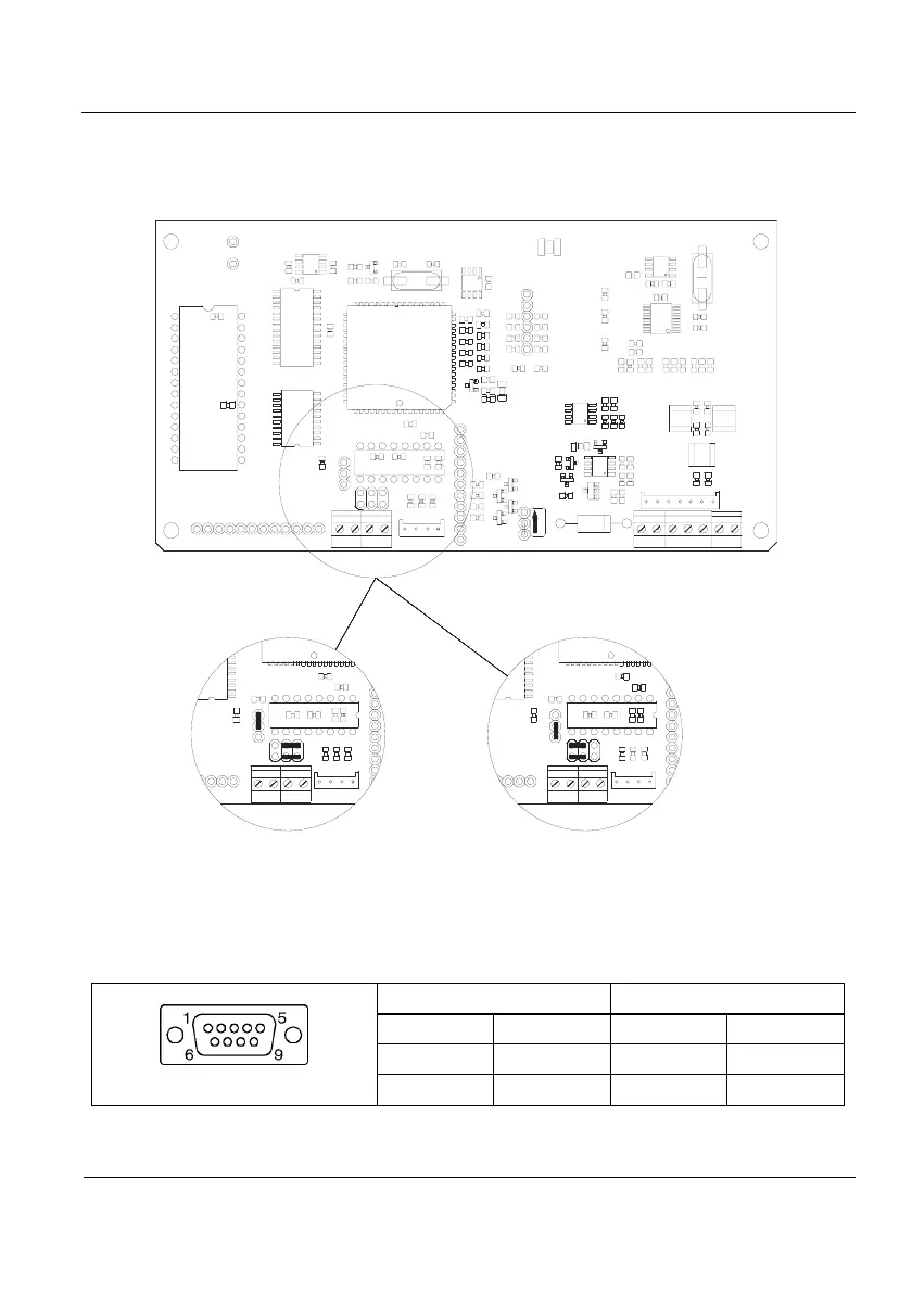
5.7 Jumpers’ position RS-232
If the equipment has multioption board (Multi1 or Multi2) the positions of jumpers J4
and J8 have to be changed as indicated in figure 5.7.1
LOCK
+
+
J4
J8 J8
J4
J8
J4
Normal Position Position for equipements
with Multi1 or Multi2
board
Figure 5.7.1 Jumpers’ position
5.8 Remote Display Connection
The remote display connection to indicator is made using the RS-232 (Rx/Tx)
communication connectors connected as follows:
SUB-D 9 aerial female connector
Pin allocation
welding's side view
INDICATOR REMOTE DISPLAY
PIN SIGNAL PIN SIGNAL
3 TxD 2 RxD
5 GND 5 GND
Table 5.8.1 Indicator-Remote Display Connection Allocation