CUTMASTER 40MM
SERVICE 5-14 Manual 0-5085
I. START ERROR FAULT. The FAULT
Indicator and 75 PSI LED flashing.
1. Start signal is active when SW1 is turned to ON
position.
a) START can be active for one of the following:
• Handtorchswitchheldclosed
• Handpendantswitchheldclosed
• CNCSTARTsignalisactivelow
Release the START signal source.
2. Problem in the torch and leads switch circuit
a) Check continuity of torch switch circuit at ATC
pins 3 & 4. See previous illustration.
3. Short in CNC cable
a) Check continuity
4. Defective Logic PCB 3
a) Measure voltage at Main PCB 1 between J2-16
to test point GND1 for 12VDC. If voltage is
present, replace Logic PCB 3.
5. Defective Main PCB 1.
a) Replace Main PCB 1.`
J. TIP MISSING FAULT. The FAULT Indicator
and 80 PSI LED is flashing. Gas solenoid
cycles ON and OFF.
1. Torch Shield Cup is loose.
a) Tighten shield cup by hand. Do not over
tighten.
2. Torch tip, electrode, or start cartridge missing.
a) Turn OFF power supply. Replace missing
part(s).
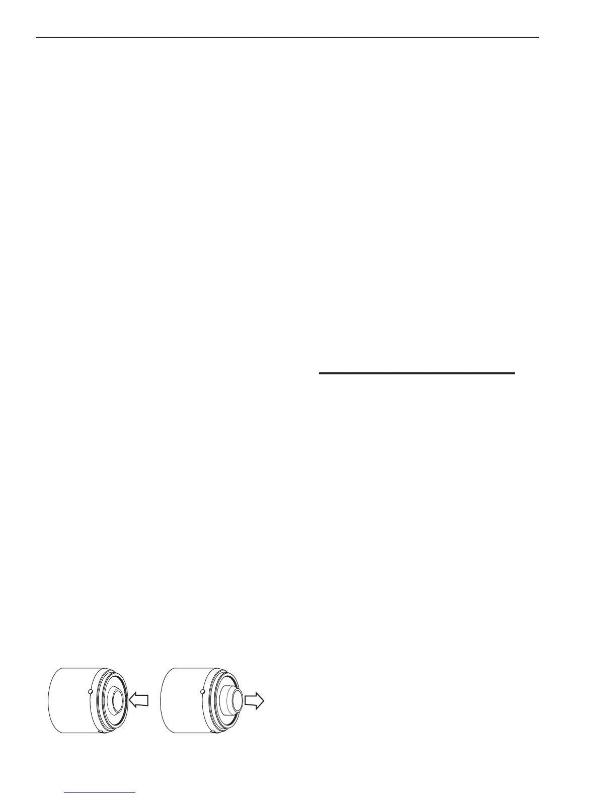
3. Start Cartridge is stuck.
a) Turn OFF power supply. Bleed down the sys-
tem. Remove the shield cup, tip,start cartridge
and electrode. Check the lower end unit of the
start cartridge for free movement. Replace the
cartridge if the lower end unit does not move
freely.
Art # A-08064_AC
Lower End Fitting
Full Compression
Spring-Loaded
Lower End Fitting at Reset
Full Extension
4. Open conductor in torch leads
a) Check continuity
5. Defective Main PCB 1.
b) Measure voltage between J2-2 connector on
Main PCB 1 to test point GND1 for 12VDC. If
voltage is present, replace Main PCB 1.
6. Defective Logic PCB 3.
a) Replace Logic PCB 3.
K. AC LED ON, yellow TEMP LED is ON, red
FAULT Indicator is flashing all three fans
turn ON.
1. Air flow through unit is restricted.
a) Provide adequate airflow. See Ventilation
Clearance Requirements section 2.04.
2. Exceeded duty cycle of the power supply.
a) Allow unit to remain ON, but at idle, with
fan running to cool power supply. See Power
Supply Specifications section 2.04 for duty
cycle information.
NOTE
When the unit is turned ON the cooling fans MOT
1-3 will remain OFF. (In earlier units MOT 1 will turn
ON for one (1) second and then turns OFF) The fans
will turn ON when a START signal (Torch Switch,
Remote Pendant switch, or CNC START) is active
and will remain ON for ten (10) minutes after the
START signal is removed. If an over temperature
condition occurs, the fans will continue to run while
the condition exists and for a ten (10) minute period
after the condition is cleared.
3. Defective 40A PCB 5.
Measure for 12VDC on the 40A PCB 5 between
J4-4 to J4-10. Replace 40A PCB 5 if voltage is
not present.
4. Defective Main PCB 1.
a) Measure for 12VDC on Main PCB 1 between
J2-21 to TP GND1. Replace Main PCB 1 if volt-
age is not present.
5. Defective Logic PCB 3.
a) Change Logic PCB 3.

 Loading...


