CUTMASTER 40MM
Manual 0-5085 5-23 SERVICE
H. PCB 5 Output Diode D2 Test
1. Disconnect transformer wires from Main PCB 5
terminal SEC1.
2. Using an ohmmeter perform the following checks:
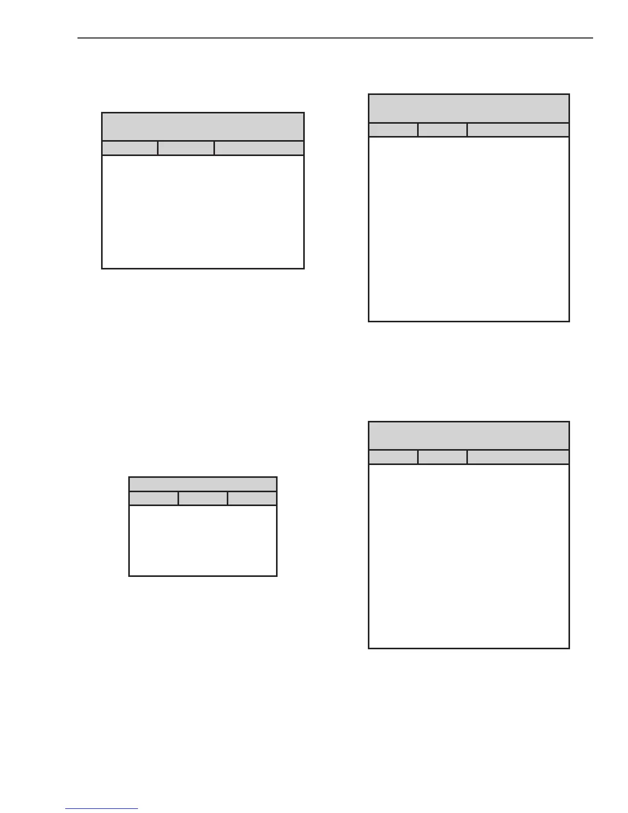
PCB 5 – D2
Test points located on PCB 5
Meter (+) Meter (-) Indication
CHOKE1 SEC1 Forward Bias
CHOKE1 SEC2 Forward Bias
SEC1 CHOKE1 Reversed Bias
SEC2 CHOKE1 Reversed Bias
+OUT_1 SEC1 Reversed Bias
+OUT_1 SEC2 Reversed Bias
SEC1 +OUT_1 Forward Bias
SEC2 +OUT_1 Forward Bias
I. PCB 1 Pilot IGBT Test
1. Disconnect wire E35 from Main PCB 1 terminal
TIP1.
2. Using a multimeter with a diode test scale, place
the positive probe on PCB 1 terminal TIP1 and
the negative probe on PCB 1 terminal WORK1
and check for a forward Biased diode reading.
3. If the test reveals a failed component, replace
Main PCB 1. If no problem is found, reconnect
wire to Main PCB.
J. PCB 2 Capacitor / Relay Test (with PCB 2
removed from the unit)
1. Using an ohmmeter perform the following checks:
PCB2Capacitor&RelayTest
Meter + Meter - Indication
MTH2 MTH4 Charging
MTH8 MTH7 Charging
MTH7 MTH4 Open
MTH8 MTH2 Open
MTH8 MTH4 Open
Most meters will show a charging action. Initially a
low resistance will be shown and then the resistance
will start to increase. If the meter probes are reversed
the reading will decrease to zero, then start charging
in the opposite polarity.
2. If test reveals a failed component, replace Capaci-
tor PCB 2.
K. PCB 1 Input Diode Test. (With PCB 2
removed form unit)
1. Using an ohmmeter perform the following checks:
Input Diode Module D1 on PCB 1
Test points located on PCB 1
Meter (+) Meter (-) Indication
AC1 TP2 Forward Biased Diode
AC2 TP2 Forward Biased Diode
AC3 TP2 Forward Biased Diode
TP2 AC1 Reverse Biased Diode
TP2 AC2 Reverse Biased Diode
TP2 AC3 Reverse Biased Diode
TP8 AC1 Forward Biased Diode
TP8 AC2 Forward Biased Diode
TP8 AC3 Forward Biased Diode
AC1 TP8 Reverse Biased Diode
AC2 TP8 Reverse Biased Diode
AC3 TP8 Reverse Biased Diode
TP8 TP2 2 Forward Biased Diodes
2. If the test reveals a failed component, replace
Main PCB 1.
L. PCB 5 Input Diode Test. (With PCB 2
removed form unit)
1. Using an ohmmeter perform the following checks:
Input Diode Module D1 on PCB 5
Test points are located on PCB 5
Meter (+) Meter (-) Indication
AC1 PMTH 1 Forward Biased Diode
AC2 PMTH 1 Forward Biased Diode
AC3 PMTH 1 Forward Biased Diode
PMTH 1 AC1 Reverse Biased Diode
PMTH 1 AC2 Reverse Biased Diode
PMTH 1 AC3 Reverse Biased Diode
PMTH 4 AC1 Forward Biased Diode
PMTH 4 AC2 Forward Biased Diode
PMTH 4 AC3 Forward Biased Diode
AC1 PMTH 4 Reverse Biased Diode
AC2 PMTH 4 Reverse Biased Diode
AC3 PMTH 4 Reverse Biased Diode
PMTH 4 PMTH 1 2 Forward Biased Diodes
2. If the test reveals a failed component, replace 40A
PCB 5.
 Loading...


