Remote Evaporator Refrigeration Service Operations
156
Solenoid Valves
NOTE: Valves that have nylon seats must be
disassembled before soldering.
Removal
1. Pump down the low side and equalize the
pressure to slightly positive.
2. Remove the access panels.
3. Remove the coil and disassemble the valve.
4. Unsolder the refrigeration lines from the
valve, and remove the valve from the unit.
Installation
1. Clean the tubes for soldering.
2. Remove the coil, disassemble the valve, and
place the valve in position.
3. Solder the inlet and outlet connections. After
the valve cools, assemble the vale and install
the coil.
4. Pressurize the refrigeration system and test for
leaks.
5. If no leaks are found, evacuate the system.
6. Install the access panels.
7. Open the refrigeration valves and run the unit.
Check the refrigerant charge and compressor
oil. Add as required.
IMPORTANT: Truck Spectrum evaporators use
Suction Line Solenoids with bleed port, where
Trailer evaporators do not. Be careful not to
intermix the two solenoids.
Liquid Return Check Valve
The unit uses an in-line check valve. The in-line
check valve is not repairable and must be replaced
if it fails. A heat sink must be used on the in-line
check valve when it is being soldered in place to
prevent damage to the neoprene seal.
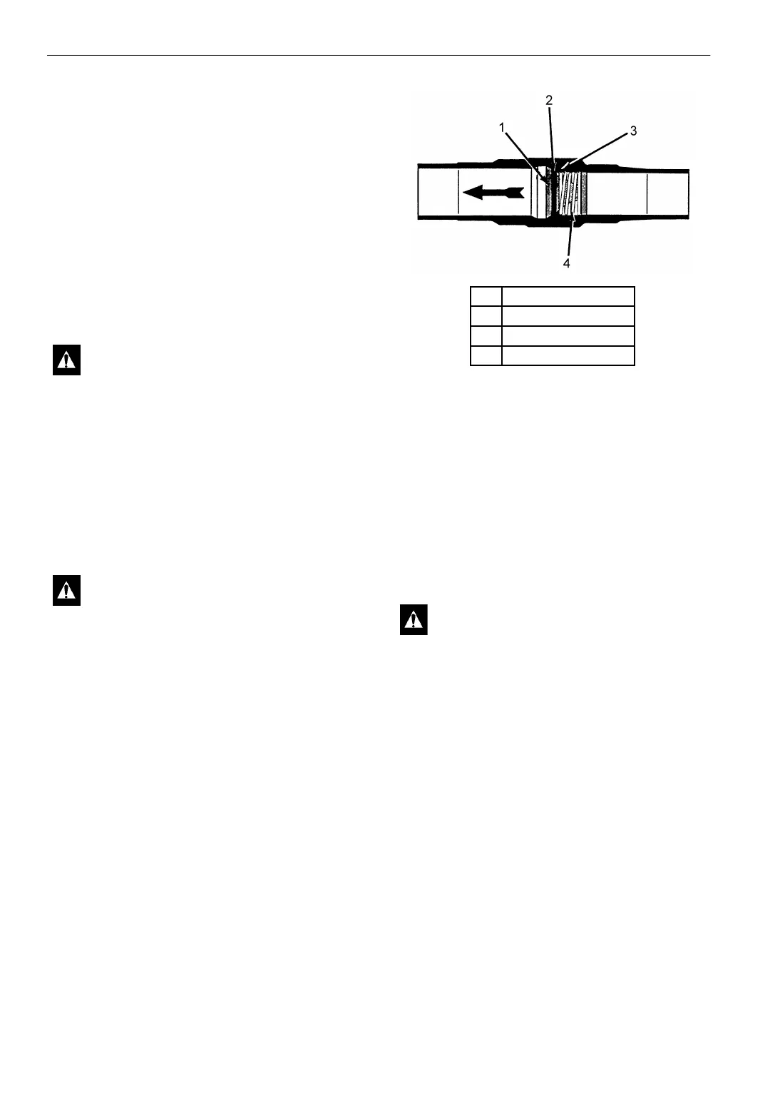
Figure 83: Cross Section of In-line Check Valve
Removal
1. Pump down the low side and equalize the
pressure to slightly positive.
2. Remove the access panels.
3. Place a heat sink on the check valve.
4. Unsolder lines and remove the check valve.
Installation
1. Clean the tubes for soldering.
2. Place the check valve in position. The arrow
on the valve body indicates the direction of
refrigeration flow through valve.
3. Place a heat sink on the check valve.
4. Solder the inlet and outlet connections.
5. Pressurize the low side and test for leaks. If no
leaks are found, evacuate the low side.
6. Install the access panels.
7. Open the refrigeration valves and place the
unit in operation. Check the refrigerant charge
and the compressor oil. Add as required.
CAUTION: Use a heat sink to prevent
damaging the valve
CAUTION: Use a heat sink to prevent
damaging the valve.
1. Valve
2. Neoprene Seal
3. Valve Seat
4. Spring
CAUTION: A heat sink must be used on
the in-line check valve when it is being
soldered in place to prevent damage to the
neoprene seal.
AEA648