Electrical Maintenance
67
2. Disconnect one wire at the switch terminal.
Connect a test light or continuity tester to the
two terminals used on the switch.
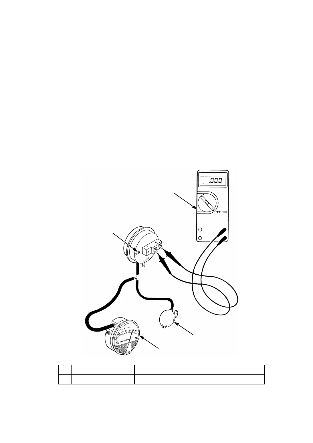
3. Connect the test equipment (P/N 204-442 and
P/N 204-494) to the hose fitting on the side of
the air switch stamped BLACK.
4. Pressurize the hose until the continuity tester
indicates a completed circuit. Now read the
dial of the test gauge. This is the setpoint of
the air switch. The correct settings is
1.00 ± 0.05 in. (25.4 ± 1.3 mm) H
2
O. Release
the pressure.
5. If the switch is out of calibration, pressurize
the hose again until the tester indicates the
correct reading. Turn the adjustment screw
until the switch closes and the continuity
tester indicates a completed circuit with the
correct reading. Release the pressure.
6. Repeat the test procedure several times to be
sure the setting is correct.
7. Remove the test equipment. Connect the wire
and air sensing tubes to the switch. The
BLACK hose from the high pressure or air
inlet side of the evaporator coil goes on the
hose fitting on the side of the air switch
stamped BLACK. The CLEAR hose from the
low pressure or air outlet side of the
evaporator coil goes on the hose fitting on the
side of the air switch stamped CLEAR.
NOTE: Route hoses for continuous slope to
avoid condensate traps.
AGA271
1
2
3
4
1. Adjustment Screw 3. Squeeze Bulb (P/N 204-494)
2. Continuity Tester 4. Pressure in Inches of Water (P/N 204-442)
Figure 22: Air Switch Testing and Adjustment