Engine Maintenance
96
Timing Individual Cylinder Injection
This procedure should be used when a poor
running engine has had all possible problems
checked but continues to run badly. If the
injection pump has been repaired or replaced, the
chance of individual cylinder timing problems has
a greater possibility of occurring.
To check individual cylinder timing, follow the
pump timing procedure but instead of changing
shims to adjust the pump timing, check the timing
of number 2 and number 3 injectors after checking
number 1. Each cylinder should be timed to its
respective flywheel timing marks.
If the injection pump plungers are not correctly
timed to each other, the pump must be removed
and sent to a diesel injection equipment repair
shop for calibration.
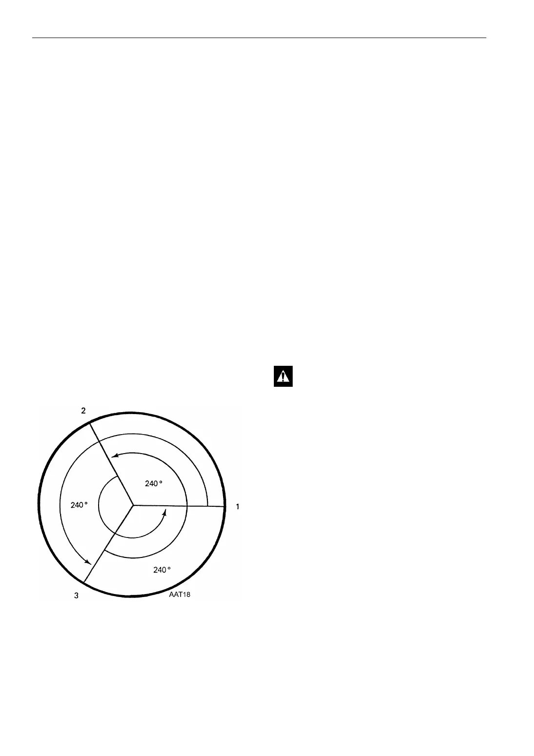
NOTE: The order of the flywheel timing marks
is 1, 2, 3, but the firing order is 1, 3, 2. This is
because the engine fires every 240 degrees of
crankshaft rotation. Therefore, when checking
individual cylinder timing check number 1 first
then rotate the engine past number 2 to number
3 and check number 3. Then rotate the engine
past number 1 to number 2 and check number 2.
Figure 49: Individual Cylinder Timing and Firing
Order
Fuel Limit Screw and Maximum
Speed Stop Screw
The fuel limit screw and the maximum speed stop
screw are both covered with anti-tamper caps and
are not adjustable.
Engine Valve Clearance
Adjustment
The valve clearance should be checked after the
first 500 hours of engine operation and every 2000
hours after that. It is very important to have the
valves adjusted properly. If the valve clearance is
too small, that cylinder may loose compression,
misfire, and burn the valve and valve seat. If the
valve clearance is too large, the valve will be
noisy and the valve and rocker arm may wear
abnormally. Adjust the valves at room
temperature with the valves closed.
1. Remove the rocker arm cover.
2. Torque the cylinder head bolts to the proper
torque.
3. Rotate the engine in the normal direction of
rotation (counterclockwise from the flywheel
end) until the number 1 cylinder is at top dead
center of the compression stroke.
a. Check the rocker arms and push rods on
the number 1 cylinder.
b. If the rocker arms and push rods are loose,
the number 1 cylinder is at top dead center
of the compression stroke.
c. If the rocker arms and push rods are tight,
the number 1 cylinder is at top dead center
of the exhaust stroke. Rotate the engine
360 degree to place the number 1 cylinder
at the top dead center of the compression
stroke.
CAUTION: Before turning the engine by
hand, loosen all the injection lines at the
injection nozzles to prevent any possibility
that the engine might fire.