Electrical Maintenance
72
Field Test Procedure for
Multi-Temperature In-Cab TG-V
Controllers
Use tester P/N 204-831.
1. Connect the end of the tester marked “DUAL”
to the multi-temperature controller.
2. Power up the controller by connecting the
tester leads to a 12 volt dc power supply.
3. Press the controller’s
ON key to display all
segments.
NOTE: Both screens must be on to properly
test the multi-temperature controller.
a. The Whisper icon must be displayed. If
not, press the
WHISPER MODE key. Alarm
Code 19 will be recorded if the Whisper
icon is not displayed.
b. If the Alarm icon is displayed, press the
SELECT key to display the alarm and press
the
ENTER key to clear the alarm.
4. Press the
SELECT key to display the setpoint(s)
and adjust the setpoint(s) to 80 F (27 C). Both
setpoints must be adjusted to 80 F (27 C) to
properly test the multi-temperature controller.
NOTE: The controller must be set to display
temperatures in the Fahrenheit scale. The
test WILL NOT work if the controller is
displaying temperatures in the Celsius scale.
Refer to the Controller Operating and Setup
Manual for information about changing the
displayed temperature scale.
5. With the setpoint of 80 F (27 C) displayed on
the screen, press the following keys
simultaneously:
•
SELECT key.
• UP ARROW key.
• WHISPER MODE key.
6. The display will read “FT”. The
multi-temperature controller will display “FT”
on the left screen.
a. All other icons will be Off.
b. The red, Power Cord LED will begin to
flash on and off.
c. All icons will then turn On for a few
seconds.
d. Then the display will count from 1 to 15
(left screen on multi-temperature
controller).
e. The display will then read PS for pass, or
FC for fail.
f. Press the
OFF key to exit the test.
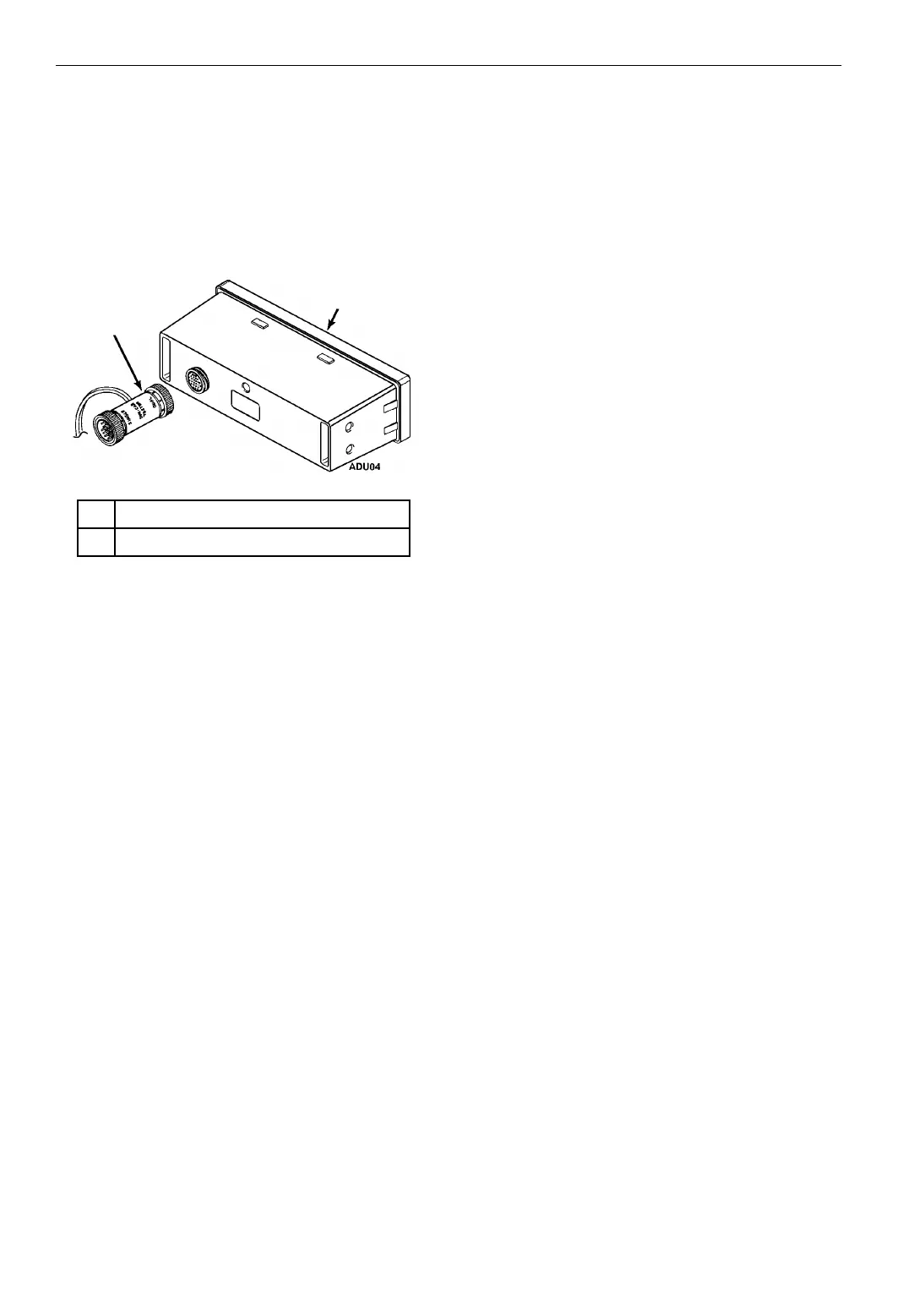
1. Tester Side “DUAL” Connections
2. Multi-Temperature Controller
Figure 26: Connecting Tester to Controller
1
2