Engine Maintenance
90
Troubleshooting the Fuel Solenoid
System
NOTE: The fuel solenoid pull-in coil may
require 18 to 25 amps to turn on the fuel. The
unit’s battery must be in good condition. If the
battery has enough power to crank the engine
over, it has enough power to energize the fuel
solenoid pull-in coil.
If you suspect that the engine does not run
because the fuel solenoid is not operating
correctly, use the following procedure:
1. Disconnect the 20 wire from the reset switch
so the reset switch will not trip.
2. Disconnect the fuel solenoid wire connector
from the main wire harness.
3. Remove the CYCLE-SENTRY module from
the option board to prevent the Auto Start
system from preheating and cranking the
engine.
4. Place the Diesel/Electric switch in the Diesel
position. Place the CYCLE-SENTRY switch
(if so equipped) in the Cont Run position.
5. Place the On/Off switches in the On position
and press the
ON key to turn the unit On.
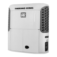
6. Check the voltage on the 8D circuit (pin A) in
the main wire harness connector for the fuel
solenoid. Refer to the following illustrations
to identify the pins in the wire connectors.
Figure 43: Main Wire Harness Connector Pin
a. If battery voltage is not present on the 8D
circuit, check the 8D circuit and the
related circuits and components for a fault.
b. If battery voltage is present on the 8D
circuit, go to step 7.
7. Check the CH circuit (pin C) in the main wire
harness at the fuel solenoid connector for
continuity to a good chassis ground.
a. If there is no continuity between the CH
circuit and a good chassis ground, check
the CH wire for an open circuit.
b. If there is continuity between the CH
circuit in the main wire harness at the fuel
solenoid wire connector and a good
chassis ground, go to step 8.
8. Place a jumper wire between the black wire
(CH—pin C) in the fuel solenoid connector
and a good chassis ground.
9. Test the pull-in coil by momentarily placing a
jumper between the white wire (8DP—pin B)
in the fuel solenoid connector and the 2
terminal at the control circuit. The fuel
solenoid should make a definite click when
the pull-in coil is energized and should click
again when the pull-in coil is de-energized.
NOTE: The pull-in coil will draw 18 to 25
amps so do not leave the jumper connected to
the white wire (8DP—pin B) for more than a
few seconds.
a. If the pull-in coil does not energize, check
the resistance of the pull-in coil by placing
an ohmmeter between the white wire
(8DP—pin B) and the black wire (CH—
pin C) in the fuel solenoid connector. The
resistance of the pull-in coil should be 0.5
to 0.7 ohms. If the resistance of the pull-in
coil is not in this range, replace the fuel
solenoid.
NOTE: If the pull-in coil fails, make sure to
replace the fuel solenoid relay with a Potter
& Brumfield relay (P/N 44-9111).
b. If the pull-in coil does energize, go to step
10.
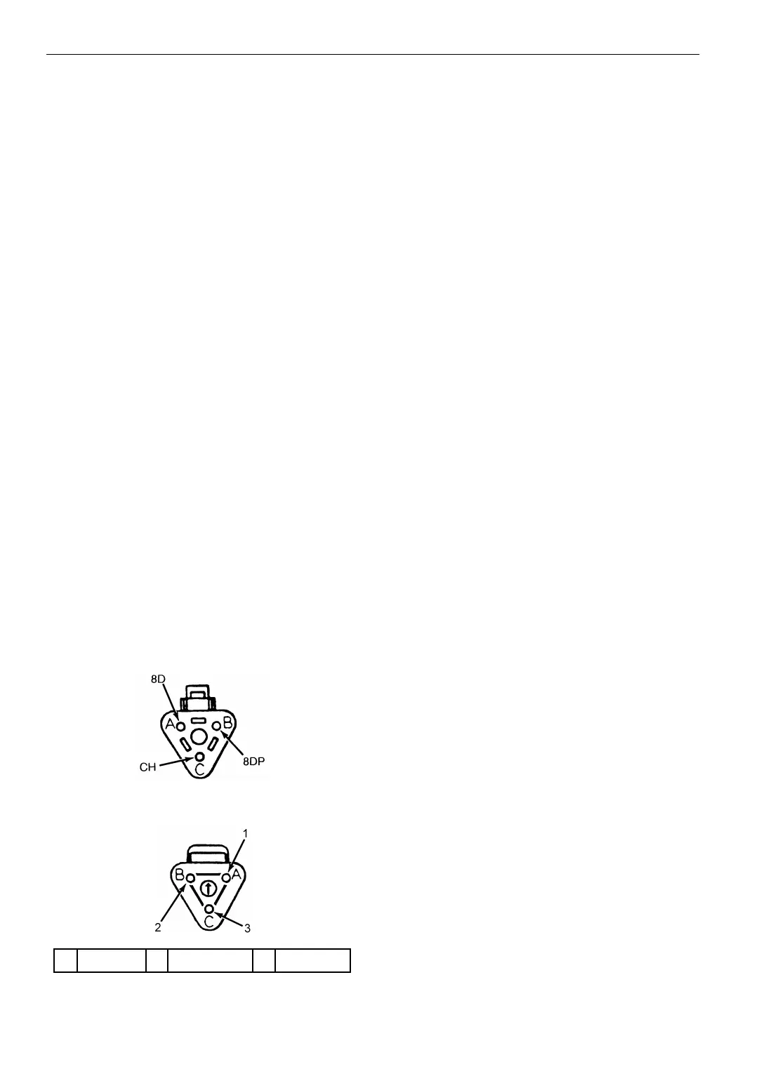
1. Red (8D) 2. White (8DP) 3. Black (CH)
Figure 44: Fuel Solenoid Connector Pin
AEA633