Electrical Maintenance
66
Defrost System Components
Defrost Termination Switches
Each electronic defrost termination switch uses
solid state components to control the Defrost
cycle. A switch is mounted in each evaporator and
controls the Defrost cycle in response to the
evaporator coil temperature. The switch is closed
when the evaporator coil temperature is below
42 F (6 C), completing the Defrost circuit to
ground and preparing the electrical system for the
Defrost cycle.
When the unit does shift into a Defrost cycle, the
fans stop, and heat from the hot refrigerant gas
melts the frost from the evaporator coil. The
switch opens and terminates the Defrost cycle
when the evaporator coil temperature rises to 52 F
(11 C).
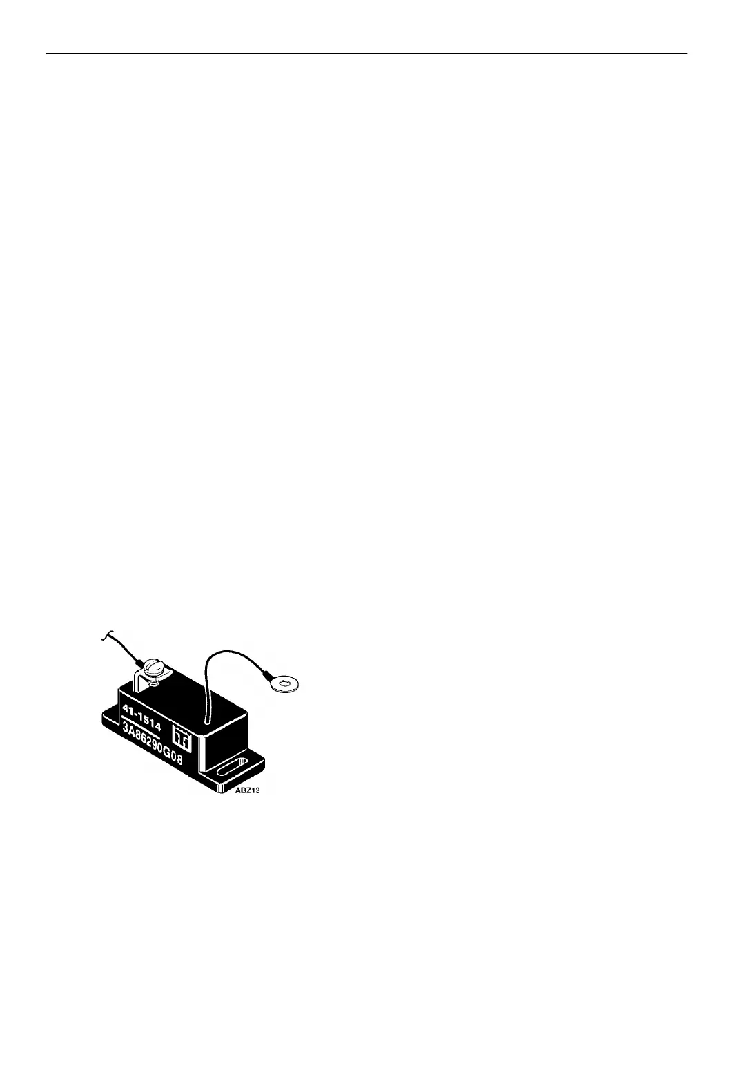
Installation: The proper polarity must be observed
when installing the defrost termination switch.
The wire from the switch is negative and must be
attached to the chassis ground of the unit. This
chassis ground wire must be grounded on a screw
separate from the switch mounting screws or an
improper ground may result. The 12 wire from the
unit attaches to the terminal mounted solid on the
switch. If the polarity is reversed on the device, it
will conduct continuously and act like a switch
that is stuck closed.
Figure 21: Defrost Termination Switch
Defrost Termination Switch Bench Test:
1.Connect
a test light between the screw terminal on the
switch and the positive battery terminal.
NOTE: Attempting to test the electronic
defrost termination switch with an ohmmeter
is generally not satisfactory because of the
low voltage available at the meter leads.
2. Connect the negative lead of the switch to the
negative battery terminal.
3. Raise the temperature of the defrost
termination switch above 52 F (11 C). The
light should be off indicating an open switch.
4. Cool the defrost termination switch below
42 F (6 C). The light should come on
indicating the switch has closed.
NOTE: Allow adequate time for the
temperature change to saturate the switch
before performing the test.
Defrost Relays
The defrost relays control the operation of each
evaporator on the Defrost cycle. When the air
switch, the TG-V defrost timer, or the Manual
Defrost switch complete the circuit through the
defrost termination switch to ground, the defrost
relays energize to initiate Defrost. A holding
circuit in the TG-V keeps the unit on Defrost until
the defrost termination switch opens.
Air Switches
An air switch automatically places each
evaporator on Defrost when ice accumulation on
the evaporator coil builds up to a point where the
air flow across the coil is restricted.
Restricted air flow results in a pressure difference
between the evaporator coil inlet and outlet. The
air switch senses the pressure differential across
the coil and initiates the Defrost cycle.
The air switch is preset at the factory. Normally
readjustment is not necessary unless the switch
has been tampered with or does not function
properly due to factors affecting air circulation,
such as bulkhead construction and duct work.
Air Switch Testing and Adjustment: Before testing
or adjusting the air switch, check the clear plastic
tubing and black plastic tubing to the evaporator
coil.
Make sure they are not obstructed or crushed.
Check the probes in the evaporator housing to be
sure they are not obstructed.
1. Remove plastic sensing tubing from both sides
of the air switch.