Electrical Maintenance
73
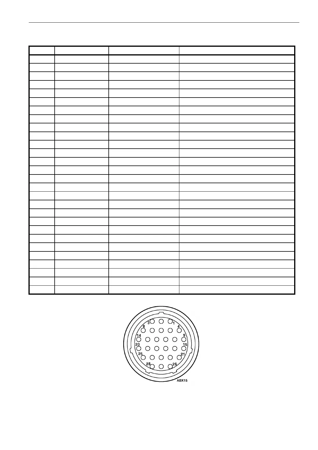
Figure 27: Connector on Back of Multi-Temperature In-Cab TG-V
Connector Pins for Multi-Temperature In-Cab TG-V
Pin # Circuit Code Harness Wire Color Code Circuit Description
1 RPS WHT/BLK/RED Zone 2 Unit On/Off
2 R10 WHT/VOIL Zone 2 Unit High Speed Relay
3 8A WHT/ORG Battery Positive
4 R38 BLUE Not Used
5 R14 YELLOW Zone 2 Unit Heat Relay
6 8A WHT/BLK/ORG Battery Positive
7 WS WHT/BLK/YEL Whisper Relay
8 14T WHT/RED Zone 1 Unit Heat Relay
9 R11 WHT/BRN Zone 2 Unit Defrost
10 ACC Accessory Wire to Truck Ignition
11 PC WHT/BLK/VOIL Power Cord (Electric Standby)
12 R7T WHT/BLK/BLU Zone 2 Unit High Speed Latching Circuit
13 10T VIOLET Zone 1 Unit High Speed Relay
14 38 WHT/BLK/BRN Not Used
15 R12 WHT/GRN Zone 2 Unit Defrost Termination Switch
16 INDL WHT/GREY Alternator Output
17 8 WHT/BRN/RED Power from On/Off Switch
18 SN WHITE Zone 1 Unit Temperature Sensor
19 SN GREEN Zone 1 Unit Temperature Sensor
20 CH WHT/BLK Battery Negative
21 11 BRN Zone 1 Unit Defrost Relay Circuit
22 12 WHT/YEL Zone 1 Unit Defrost Termination Switch
23 7T WHT/BLK/GRN Not Used
24 RSN BLK Zone 2 Unit Temperature Sensor
25 PS WHT/BLU On Relay Coil
26 7K GREY Latching Circuit after 8D
27 29 ORANGE Defrost Damper Circuit
28 RSN RED Zone 2 Unit Temperature Sensor