55
Electrical Maintenance
Alternator (Prestolite)
NOTE: Units manufactured with
CYCLE-SENTRY and alternators with integral
regulators MUST use replacement alternators
with integral regulators.
Complete the following checkout procedure
before replacing the voltage regulator or the
alternator.
• When testing alternators use accurate
equipment such as a Thermo King P/N
204-615 (FLUKE 23) digital multimeter and a
Thermo King P/N 204-613 amp clamp or an
equivalent.
• Make sure the drive belts and pulleys of the
charging system are in good condition and are
adjusted properly before testing the alternator.
Worn belts and pulleys or loose belts will
lower the output of the alternator.
• The battery must be well charged, the battery
cable connections must be clean and tight, and
the 2A and excitation circuits must be
connected properly.
CAUTION: Full-fielding alternators
with the integral regulator is
accomplished by installing a jumper from
terminal F2 to ground. Attempting to
full-field the alternator by applying battery
voltage to terminal F2 will cause voltage
regulator failure.
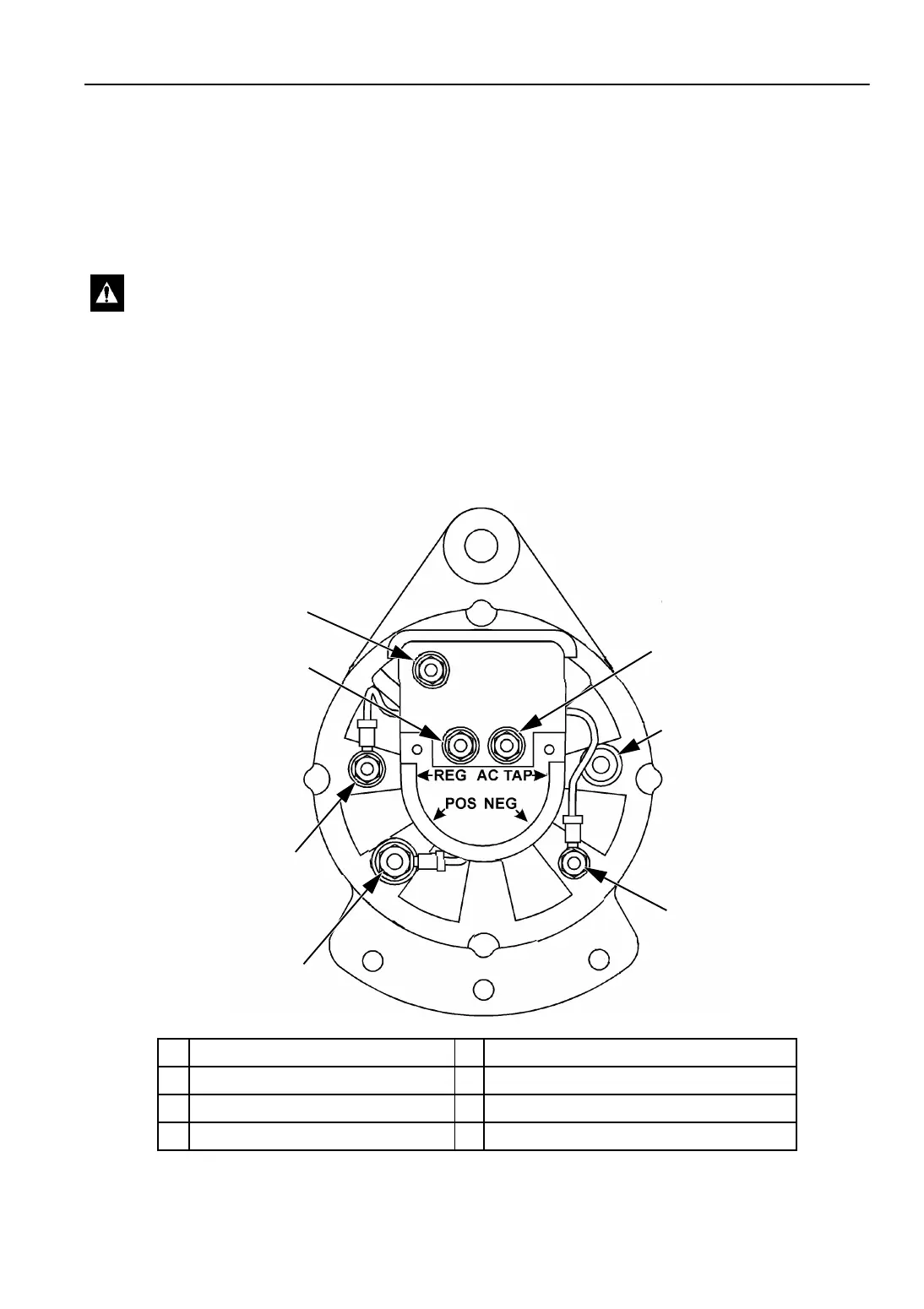
2
1
7
6
3
4
5
AJA1520
1. EXC Terminal 5. NEG—B- Terminal
2. F2 Terminal 6. POS—B+ Terminal
3. VOLT SENSE Terminal 7. REG—D+ Terminal
4. AC TAP Terminal
Figure 18: Prestolite Terminal Locations