Structural Maintenance 12-9
When a switch is in the active position, the blue wire (pole 2) is connected to the red wire (throw) and the yellow wire (pole 1)
is open.
The two micro switches are connected in parallel to the defrost damper circuit. Energizing the 29 circuit closes the damper.
Energizing the 29A circuit (29B on TCI models) opens the damper.
The blue wire from the outer switch and the yellow wire from the inner switch are connected to the 29 circuit at the connector on
the damper motor assembly.
The yellow wire from the outer switch and the blue wire from the inner switch are connected to the 29A (or 29B) circuit at the
connector on the damper motor assembly.
The red wires from both switches are connected to the positive pole of the damper motor. The negative pole of the damper motor
is connected to the CH circuit through a diode.
NOTE: The damper motor is sensitive to polarity. If the motor leads are reversed, the motor will rotate in the opposite
direction. This will damage the micro switches and cause erratic operation of the defrost damper.
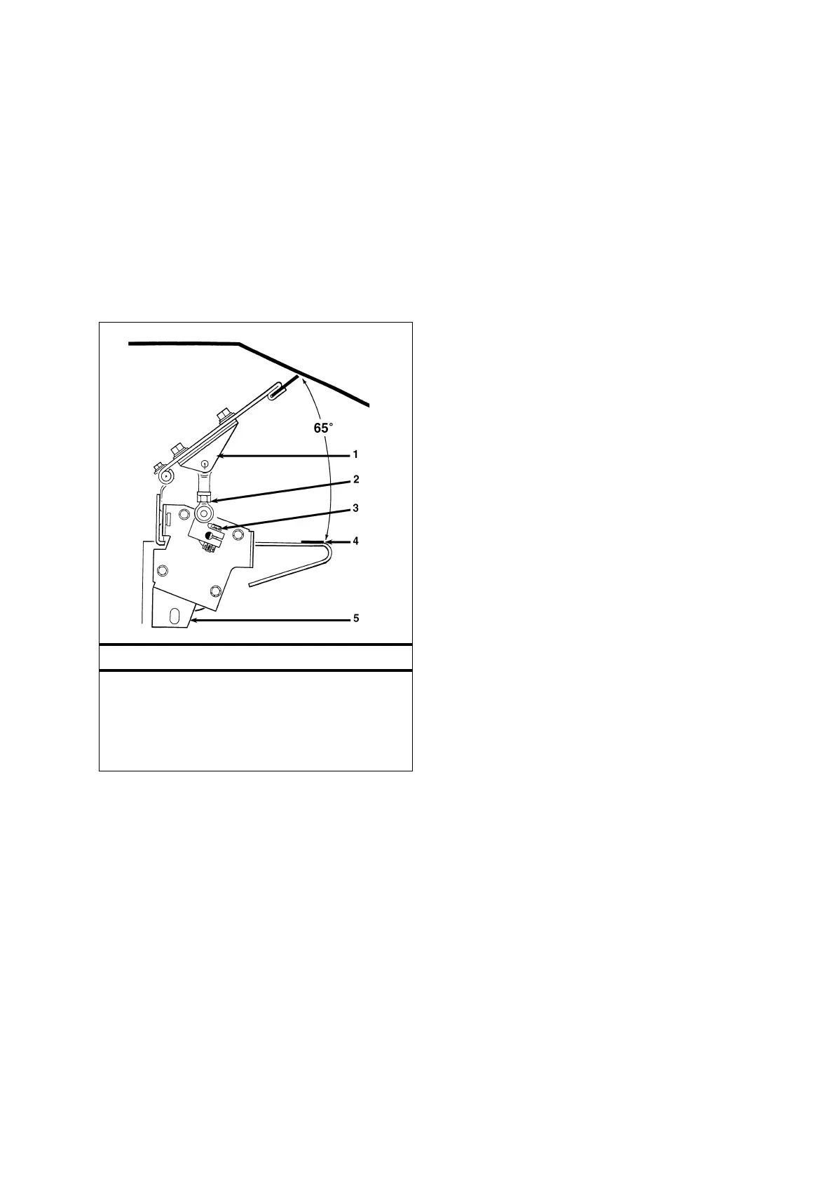
Defrost Damper Closed – SL
1. Damper Door Bracket*
2. Ball Joint Link
3. Damper Link
4. Non-freeze Strip
5. Damper Motor Bracket**
*Adjusts Arc of Damper Operation
**Adjusts Damper Vertically
 Loading...