Structural Maintenance 12-10
Damper Closing Logic
Defrost can be initiated manually or automatically when the evaporator coil temperature is below 3 C (TG-IV), 6 C (TG-V) or
7 C (TG-VI, µP-IV, µP-V or µP-VI). When defrost is initiated, the damper relay (K3 or D3) is energised. The 29 circuit is then
energised by the 2AA (or 2A or 8VF) circuit through the damper fuse (F3) and the normally open contacts in the damper relay.
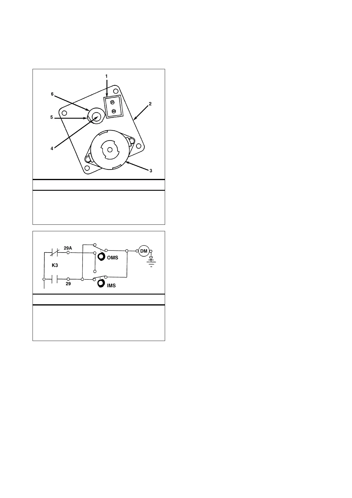
Damper Motor Assembly (Motor End) – SL
1. Micro Switches
2. Gear Case
3. Electric Motor
4. Output Shaft
5. Inner Cam
6. Outer Cam
Damper System Schematic – SL
DM Damper Motor
IMS Inner Micro Switch
OMS Outer Micro Switch
K3 Damper Relay
NOTE: 29A circuit is 29B on TCI models.
 Loading...