Structural Maintenance 12-11
At this point the outer cam is in contact with the outer micro switch and the outer micro switch is in the active position. The 29
circuit is connected to the damper motor through the outer micro switch.
The outer cam leads the inner cam by 20 degrees, therefore the inner cam is not in contact with the inner micro switch and the
inner micro switch is in the normal position. The 29 circuit is also connected to the damper motor through the inner micro switch.
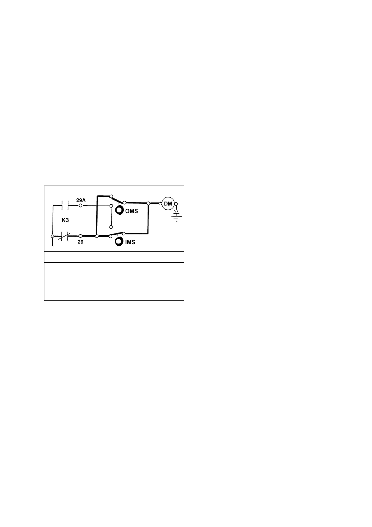
Two circuits are available to provide power to the damper motor when defrost is initiated (see “Two Initial Micro Switch Circuits
Close Damper” illustration).
As the damper motor rotates, the inner cam makes contact with the inner micro switch and places the inner micro switch in the
active position. The 29 circuit is no longer connected to the damper motor through the inner micro switch. A single circuit through
the outer micro switch is now providing power to the damper motor (see “Outer Micro Switch Circuit Still Closing Damper”
illustration).
The damper motor continues to rotate until the outer cam leaves the outer micro switch and the outer micro switch returns to the
normal position. The 29 circuit is no longer connected to the damper motor through the outer micro switch. No power is reaching
the damper motor and the damper motor stops. The damper is now in the closed position. Open circuits stop the damper motor
in the closed position (see “Micro Switch Circuits When Damper is Closed” illustration).
Damper Opening Logic
Defrost is terminated when the evaporator coil temperature rises to 9 C (TG-IV), 11 C (TG-V) or 14 C (TG-VI, µP-IV, µP-V or
µP-VI).
When defrost is terminated, the damper relay (K3 or D3) is de-energised. The 29A (or 29B) circuit is then energised by the
2AA (or 2A or 8VF) circuit through the damper fuse (F3) and the normally closed contacts in the damper relay.
Two Initial Micro Switch Circuits Close Damper – SL
DM Damper Motor
IMS Inner Micro Switch
OMS Outer Micro Switch
K3 Damper Relay
NOTE: 29A circuit is 29B on TCI models.
 Loading...