Time Electronics User Manual
5051 Plus and 7051 Plus Multifunction Calibrators v2.1
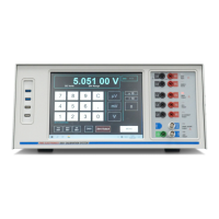
xx51+ Multifunction Calibrators Page 3 of 64
Contents
1. Introduction ................................................................................................................... 5
1.1. Features ................................................................................................................................................... 5
1.2. Calibration Capabilities .......................................................................................................................... 5
2. Specifications ................................................................................................................ 6
2.1. Calibrator (Source) ................................................................................................................................. 6
2.2. 6.5 Digit Multimeter (measure) .............................................................................................................. 6
2.3. 7051 Control Centre Details ................................................................................................................... 7
2.4. 7051 General Specifications .................................................................................................................. 7
2.5. 5051 Control Centre Details ................................................................................................................... 8
2.6. 5051 General Specifications .................................................................................................................. 8
3. General Safety Precautions ......................................................................................... 9
4. General Operation Precautions ................................................................................... 9
5. 7051 Plus ...................................................................................................................... 10
5.1. Standard 7051Plus ............................................................................................................................... 10
5.2. 7051Plus With CCPAD Option ............................................................................................................. 10
5.3. 7051 Terminal Panel ............................................................................................................................. 11
6. 5051 Plus ...................................................................................................................... 12
6.1. 5051 Plus Important Information ......................................................................................................... 12
6.2. 5051 Terminal Panel ............................................................................................................................. 13
7. Operation ..................................................................................................................... 14
7.1. Operating the xx51 as a calibrator ...................................................................................................... 15
7.2. DC Voltage ............................................................................................................................................ 16
7.2.1. Setting the Output Value .......................................................................................................... 17
7.2.2. DC Voltage Connection Diagram ............................................................................................. 18
7.2.3. HV interlock and ramping ......................................................................................................... 19
7.2.4. Varying the Output Level .......................................................................................................... 20
7.2.5. Using Deviation ........................................................................................................................ 20
7.2.6. Monitoring the Internal Temperature ........................................................................................ 22
7.3. DC Current ............................................................................................................................................ 23
7.3.1. Current Output Terminals ......................................................................................................... 23
7.3.2. DC Current Connection Diagrams ............................................................................................ 24
7.3.3. Output Error .............................................................................................................................. 25
7.3.4. High Current Interlock and Ramping ........................................................................................ 25
7.4. AC Voltage ............................................................................................................................................ 26
7.4.1. Frequency Limits ...................................................................................................................... 26
7.4.2. HV Interlock and Ramping ....................................................................................................... 26
7.4.3. Low Output Range – 20mV ...................................................................................................... 26
7.4.4. AC Voltage Connection Diagrams ............................................................................................ 27