TD80™ Level Gauging and Overfill Prevention System Product Manual
Rev. 2, August 4, 2015/ TD80 and Overfill Prevention System Troubleshooting Page 77
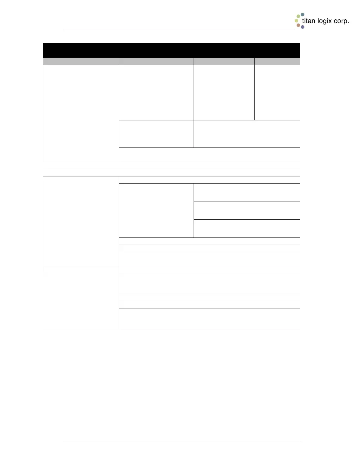
7. Fill Alarm remains inactive.
a. Check Fill alarm setting
on 5332(E). Confirm that
the 5332(E) is flashing the
level to indicate an active
alarm.
i. Confirm that the PTO
signal is active by either a
switch operation or
permanently enabled
through wiring.
If the PTO
signal does
activate, then
troubleshoot
the PTO
signal wiring
and
components.
ii. If the 5332(E) does not
flash at the desired fill
level
Confirm and reset the Fill alarm
setting. If this does not fix the
problem, then the Finch Display may
be faulty, replace the unit.
iii. If the Finch Display flashes at the alarm setting then
troubleshoot the Fill alarm wiring and components.
b. Confirm that the J1 shorting jumper is installed correctly.
c. Confirm that the J9 Fill/Fall jumper is installed correctly.
d. For Fill alarms
energized by a ground
from the 5332(E)
i. Check for power at the Red light and/or Horn.
ii. Clip the test light to
ground and probe all Fill
alarm circuit points to
activate the Red light
and/or Horn. Circuit
points to confirm are as
follows:
a. At the 5332(E) FILL-COM, FILL-
NO or FILL-NC
b. At any external wiring junctions
iii. Check for a blown fuse (if installed) and replace as necessary
iv. Inspect for broken or corroded wiring and repair as necessary
v. Inspect for broken or defective horn or light and repair as
necessary
e. For Fill alarms
energized by power from
the 5332(E)
i. Check for ground at the Red light and/or Horn
ii. Clip the test light to power and probe all Fill alarm circuit points
to activate the Red light and/or Horn. Circuit points are as
described above.
iii. Check for a blown fuse (if installed) and replace as necessary
iv. Inspect for broken or corroded wiring and repair as necessary
v. Inspect for broken or defective horn or light and repair as
necessary

 Loading...