2-7
Chapter 2
NOMENCLATURE AND FUNCTIONS
32. DC power input terminal
Connect an optional DC power supply unit to
this terminal. Select the DC power supply source
with consideration given to the current power
consumption of the system the VX-3000F is to be
connected to.
(See the Instruction Manual attached to the VX-
3000DS or the VX-3150DS.)
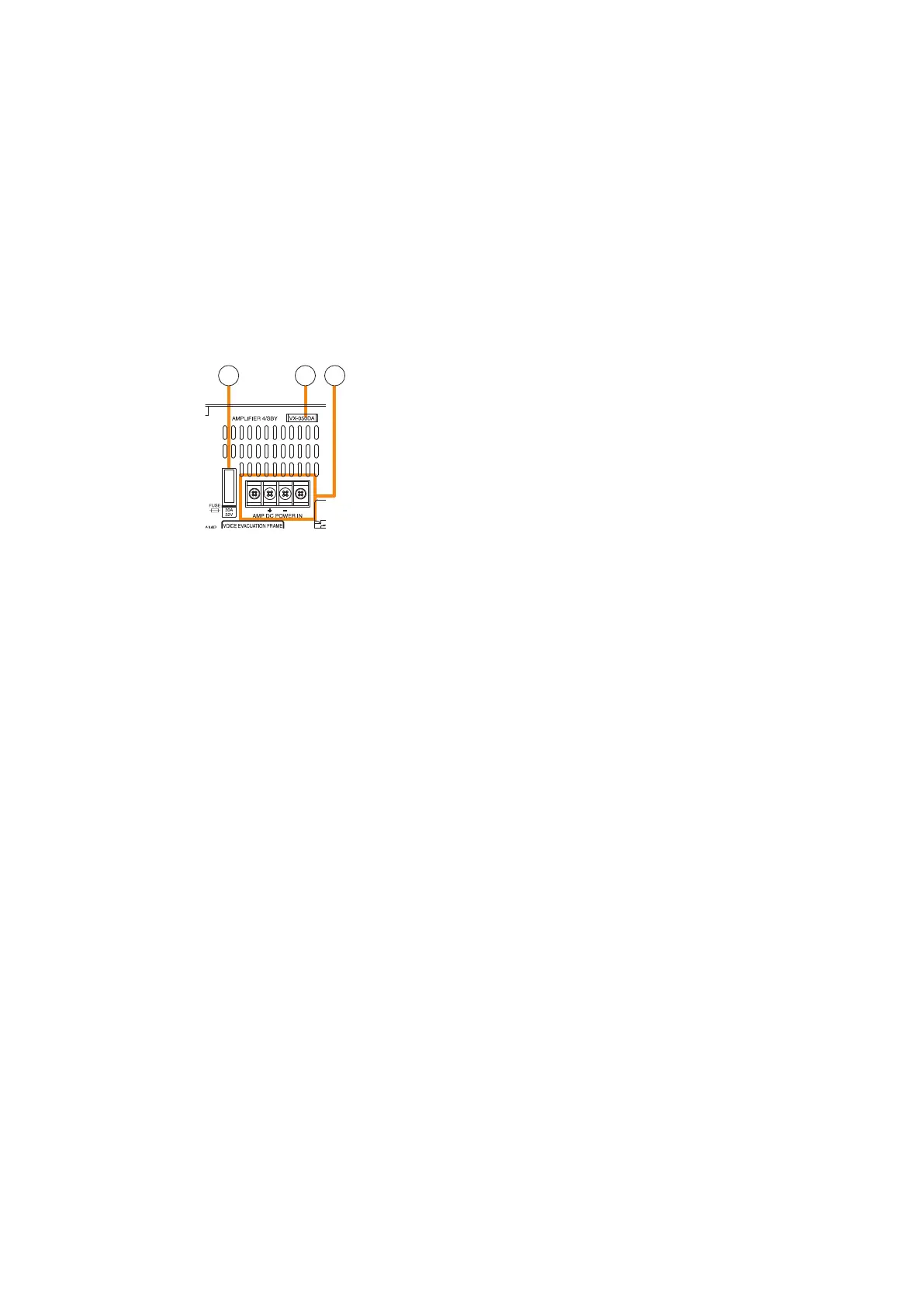
33. Fuse
When an amplier module is installed, its fuse
can be checked.
You can replace the fuse with the amplier module
installed to the VX-3000F. (See p. 2-10.)
34.Ampliermodelnumberindicationwindow
When a power amplier module is installed, you
can check its model number.
35.AmplierDCpowerinputterminal
When a power amplier module is installed, you
can check its power input terminals. (See p. 2-10.)
36. Audio input terminals
Electronically-balanced 47 kΩ, –20 dB*/–60
dB*, Terminal connectors. LINE or MIC input
can be selected, and the phantom power supply
turned on and off. (See the separate Setting
Software Instructions, "UNIT CONFIGURATION
SETTINGS.")
* 0 dB = 1 V
37. Signal ground terminal
Hum noise may be generated when external
equipment is connected to the unit. Connecting
this terminal to the signal ground terminal of the
external equipment may reduce the hum noise.
Note: This terminal is not for protective ground.
38.Standbyamplieroutputconnector
When a standby amplier is shared by multiple VX-
3000F units, connect this connector to the standby
amplier input connector of other VX-3000F.
39.Standbyamplierinputconnector
When making the VX-3000F with no standby
amplier share the standby amplier installed to
other VX-3000F, connect this connector to other
VX-3000F's standby amplier output connector.
40. MAC address
This is the MAC address* for the unit. Since
the relationship of each unit location to its MAC
address is established when setting the network
attributes, keep track of this relationship for later
use.
* The unit’s MAC address consists of 12
hyphenated alphanumeric characters.
41. Speaker output terminals
Connect speakers to these outputs.
42. ATT/Control output terminals
These terminals permit the VX-3000 system to
control other connected external equipment.
Alternatively, these terminals become attenuator
control outputs by setting.
43. Emergency control input terminal
Connect to an automatic re alarm system and
activate emergency broadcasts, play back/stop
automatic emergency announcements and reset
emergency broadcasts.
Two isolated voltage inputs which activates when
the polarity of the applied voltage (24 V DC is kept
applied to this terminal under normal condition) is
reversed.
44. DS link connectors
Connects this connector to the DS LINK IN
connector of the VX-3000DS or the VX-3150DS.
45. Analog link output connector
Connect this connector to the analog link input
connector of the other VX-3000F.
46. Analog link input connector
Connect this connector to the analog link output
connector of the other VX-3000F.
47. Control output connectors
These RJ45 connectors permit the VX-3000
system to control other connected external
equipment.
48. Control input connectors
These RJ45 connectors receive activation signals
from external equipment to enable external VX-
3000 system control.
Alternatively, these connectors become EOL
inputs by setting.
33 34 35