5-126
dummyheaddummyhead
FUEL SYSTEM
HO2S INSPECTION
SYSTEM INSPECTION
OPERATION TEST
1. HO2S operation test 1
Turn the combination switch OFF and disconnect
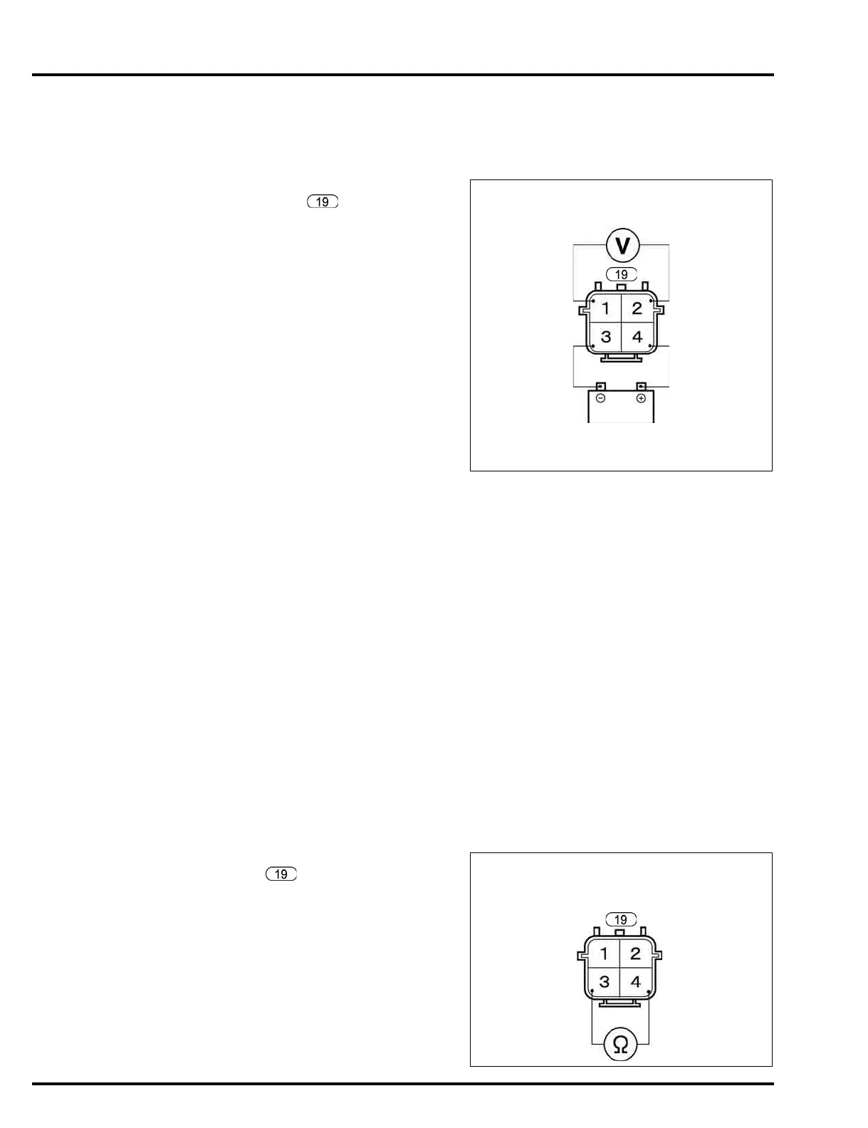
the HO2S 4P connector .
Connect the battery positive (+) cable to the sensor
side No.4 (White) terminal and the battery negative
cable (–) to the sensor side No.3 (White) terminal of
the HO2S 4P connector respectively.
Start the engine and let it run at 3,000 min
-1
(rpm) for
3 minutes or more under no load.
Snap the engine throttle with the engine speed in
the range between idle speed and 4,000 ± 500 min
-1
(rpm).
Let the engine idle for 1 minute or more.
Make sure that the voltage is above 0.6 V at the
No.1 (Black) terminal and No.2 (Gray) terminal of
the HO2S sensor side 4P connector.
If the voltage is temporarily below 0.6 V, recheck the
above inspection after engine idle for 1 minute or
more.
• The normal voltage at the idle speed is above 0.6
V.
Depending on the condition of the warm-up, the
voltage may become temporarily less than 0.6 V.
Does the voltage above 0.6 V exist?
YES – GO TO STEP 2.
NO – Faulty HO2S.
2. HO2S operation test 2
Snap the engine throttle with the engine speed in
the range between idle speed and 4,000 ± 500 min
-1
(rpm).
Or let it run at 4,000 ± 500 min
-1
(rpm) under no load
then quickly close the throttle valve.
Is the measurement above 0.6 V when the
throttle is fully open and below 0.6 V when the
throttle is fully closed?
YES – HO2S is normal.
NO – Faulty HO2S.
HO2S HEATER INSPECTION
Turn the combination switch OFF and disconnect the
HO2S 4P connector (page 10-6).
Measure the resistance between the No.3 (White) and
No.4 (White) terminals of the HO2S sensor.
HO2S 4P CONNECTOR SENSOR SIDE
SG
(Gray)
O2
(Black)
O2HT
(White)
12V BATTERY
(White)
Resistance:4 – 30 Ω
HO2S 4P CONNECTOR
SENSOR SIDE
IGP3
(White)
O2HT
(White)



 To Next Page