10-14
dummyheaddummyhead
OTHER ELECTRICAL
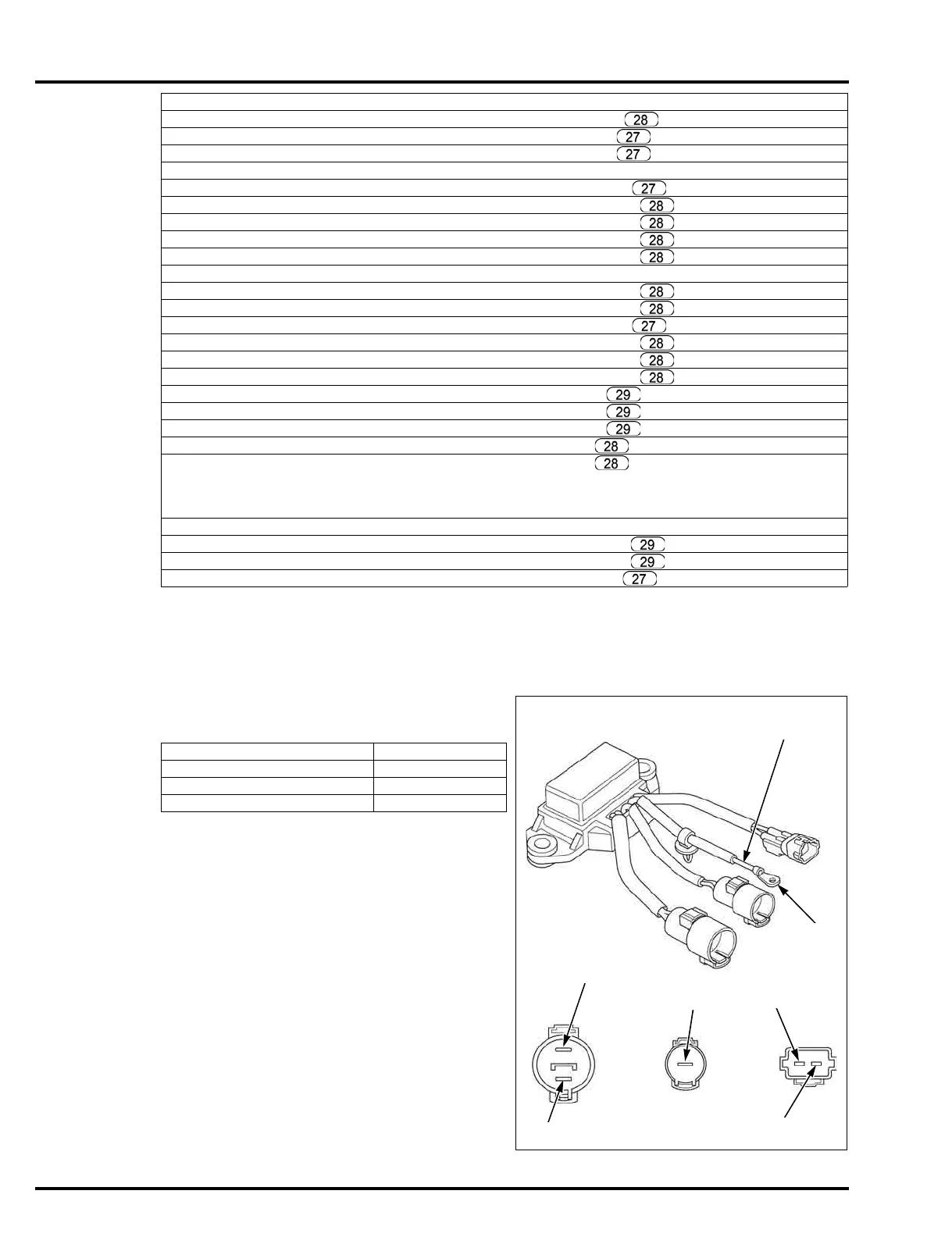
POWER TILT RELAY INSPECTION
• Disconnect the power tilt relay connectors, and
remove the relay from the outboard motor to check.
Remove the power tilt relay (page 10-6).
Check for continuity between the following terminals.
No.9 fuse (15 A) No.8 terminal and fuse/relay junction box 23P connector No.2 (INJ 6) terminal
No.9 fuse (15 A) No.8 terminal and fuse/relay junction box 8P connector No.6 (IGP 1) terminal
No.9 fuse (15 A) No.8 terminal and fuse/relay junction box 8P connector No.7 (IGP 2) terminal
No.10 fuse (10 A) No.11 terminal and main relay No.28 terminal
No.10 fuse (10 A) No.12 terminal and fuse/relay junction box 8P connector No.2 (ACG) terminal
No.10 fuse (10 A) No.12 terminal and fuse/relay junction box 23P connector No.10 (O2) terminal
No.10 fuse (10 A) No.12 terminal and fuse/relay junction box 23P connector No.11 (SVSCP) terminal
No.10 fuse (10 A) No.12 terminal and fuse/relay junction box 23P connector No.13 (SVS) terminal
No.10 fuse (10 A) No.12 terminal and fuse/relay junction box 23P connector No.14 (IGP 3) terminal
No.11 fuse (15 A) No.9 terminal and main relay No.28 terminal
No.11 fuse (15 A) No.10 terminal and fuse/relay junction box 23P connector No.23 (PHC 1) terminal
No.11 fuse (15 A) No.10 terminal and fuse/relay junction box 23P connector No.21 (PHC 2) terminal
No.11 fuse (15 A) No.10 terminal and fuse/relay junction box 8P connector No.3 (PHC 3) terminal
No.11 fuse (15 A) No.10 terminal and fuse/relay junction box 23P connector No.1 (PHC 4) terminal
No.11 fuse (15 A) No.10 terminal and fuse/relay junction box 23P connector No.15 (PHC 5) terminal
No.11 fuse (15 A) No.10 terminal and fuse/relay junction box 23P connector No.19 (PHC 6) terminal
Starter relay No.21 terminal and fuse/relay junction box 10P connector No.1 (ST) terminal
Starter relay No.22 terminal and fuse/relay junction box 10P connector No.9 (GND (NTSW)) terminal
Starter relay No.24 terminal and fuse/relay junction box 10P connector No.6 (ST SOL) terminal
Main relay No.25 terminal and fuse/relay junction box 23P connector No.4 (IGPR) terminal
Main relay No.26 terminal and fuse/relay junction box 23P connector No.9 (GND) terminal
• Switch the tester lead polarities to check the circuit, including a diode. The circuit is normal if there is
continuity in one direction but not the other. If there is continuity in both directions or in neither direction, the
circuit is abnormal.
Main relay No.28 terminal and fuel pump relay No.33 terminal
Fuel pump relay No.34 terminal and fuse/relay junction box 10P connector No.4 (FLR 1) terminal
Fuel pump relay No.34 terminal and fuse/relay junction box 10P connector No.5 (FLR 2) terminal
Fuel pump relay No.36 terminal and fuse/relay junction box 8P connector No.5 (FUEL PUMP) terminal
Check terminals
Between Green and Black Continuity
Between Blue and Black Continuity
Between Green and White No continuity
Between Blue and White No continuity
GROUND WIRE
White
Blue
Green
Light blue
Light green
Black
 Loading...